

Bone plate
a bone plate and plate body technology, applied in the field of bone plates, can solve the problems of increasing the weight of the bone plate, jeopardizing the stability of the bone fusion,
- Summary
- Abstract
- Description
- Claims
- Application Information
AI Technical Summary
Benefits of technology
Problems solved by technology
Method used
Image

Examples
example i
All Dimensions in mm
[0040]
A9.47T0.947R110.0382L98.512471W14.306392W23.006349D17.032338
example ii
All Dimensions in mm
[0041]
A11.58T1.158R112.2748L10.40913W15.265894W23.67619D18.599206
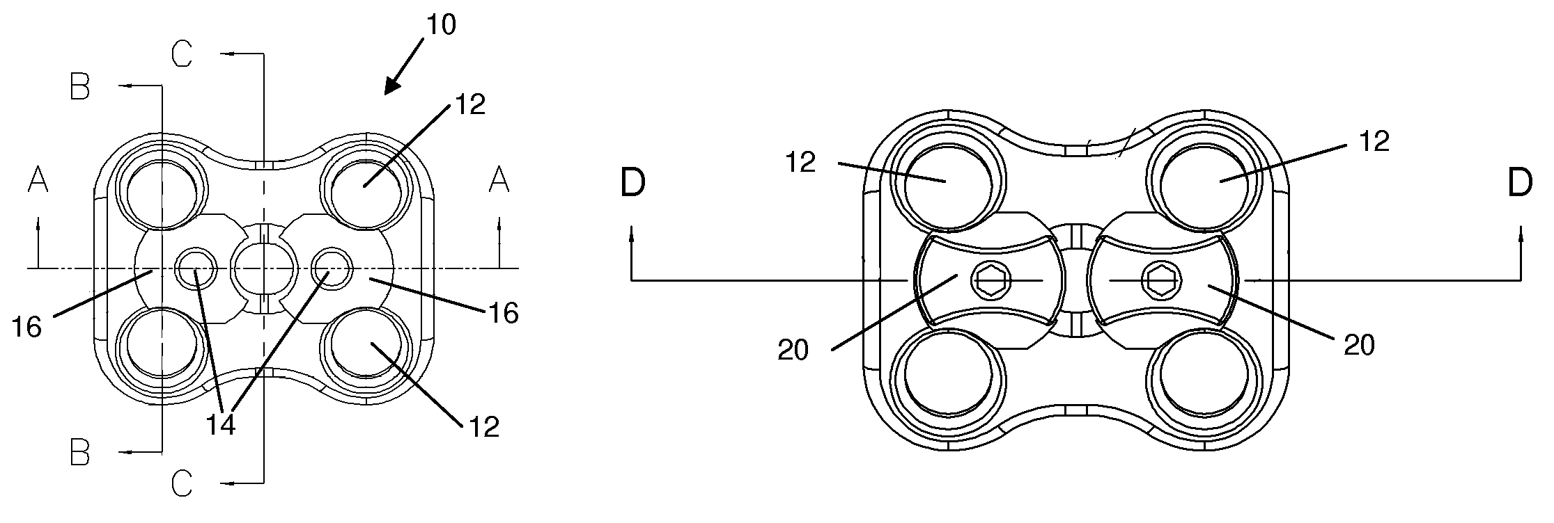
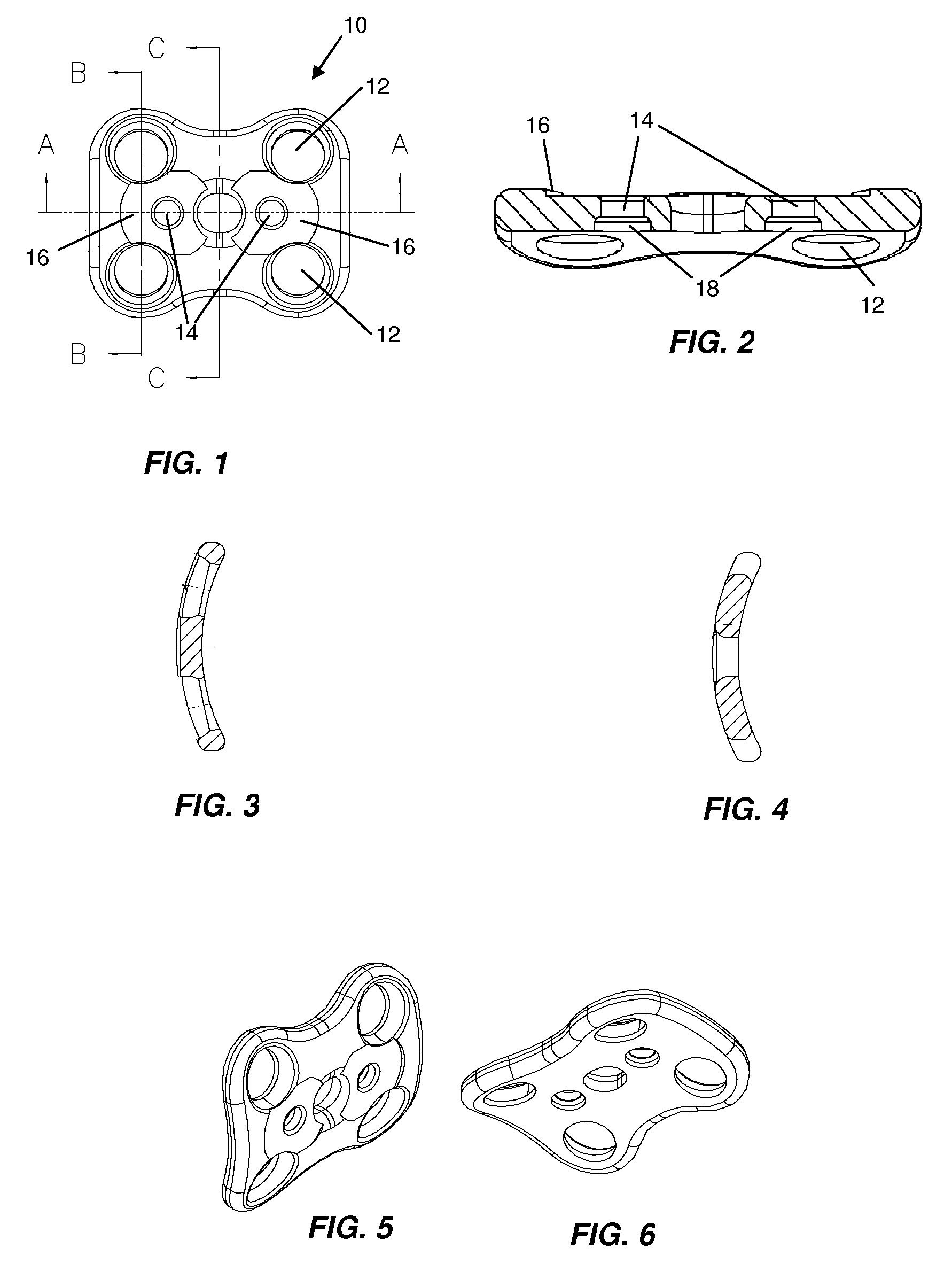
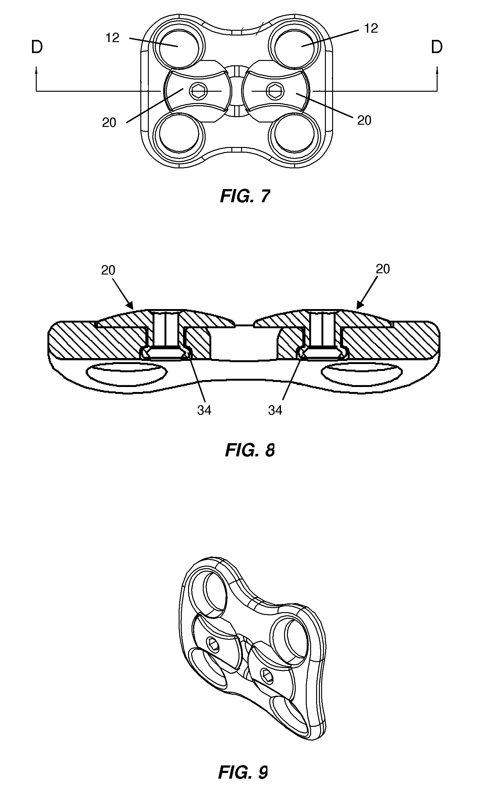
[0042]Preferably, the plate and rivets are made out of the same or different biocompatible materials, e.g., a titanium alloy, stainless steel, and the like; alternatively, a bioresorbable material can be used. The present invention is not restricted to a particular number of holes and screws in the plate, as such plates are made in different lengths to fit the patient's anatomy. By way of non-limiting examples, the plates can be 4-hole, 6-hole, 8-hole, and 10-hole plates. Each set of two holes 12, the screws for which are lockable by a common rivet 20, are separated by a distance which is greater than the distance A, so that the rivet 20 for each set of holes 12 does not interfere with the rivet for the other set of holes.
[0043]Preferably, a 4-hole plate will have two rivets, one for two holes, but one rivet per hole is also within the scope of the present invention. Further preferably, the rivet 20...
PUM
 Abstract
Description
Claims
Application Information