IP-TV broadcasting service system and method using physical layer's multicast switch

a multicast switch and broadcasting service technology, applied in the field of iptv broadcasting service, can solve the problems of delay, jitter, and difficulty in implementing the technology using existing methods, and achieve the effects of reducing the number of broadcasters, and improving the quality of broadcasting

Active Publication Date: 2010-03-09
ELECTRONICS & TELECOMM RES INST
View PDF15 Cites 10 Cited by
  • Summary
  • Abstract
  • Description
  • Claims
  • Application Information

AI Technical Summary

Benefits of technology

[0007]The present invention provides an Internet Protocol Television (IP-TV) broadcasting service system and method using a multicast switch of a physical layer, which multicasts signals bundled in a plurality of channels to an intended location without delay, jitter, or packet loss.

Problems solved by technology

Since multicasting is performed in a single channel in the IP network, a multi-protocol label switched protocol (MPLS) technology should be used to multicast signals bundled in a plurality of channels, but it is difficult to implement the technology using existing methods.
Moreover, a protocol used for controlling multicasting is complicated, and delay, jitter, and packet loss in visual signals must be minimized in order to ensure high quality.

Method used


Image

  • IP-TV broadcasting service system and method using physical layer's multicast switch
  • IP-TV broadcasting service system and method using physical layer's multicast switch
  • IP-TV broadcasting service system and method using physical layer's multicast switch

Examples


Embodiment Construction

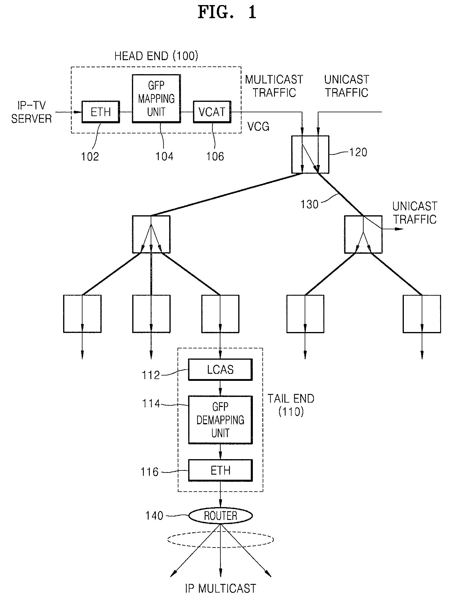
[0019]FIG. 1 is a configuration diagram of an Internet Protocol Television (IP-TV) service system network using a multicast switch of a physical layer according to an embodiment of the present invention. Referring to FIG. 1, the IP-TV service system network includes a head end 100, a tail end 110, and a multicast switch 120.

[0020]In order to transmit an Ethernet signal from an IP-TV server to a synchronous digital hierarchy / synchronous optical network (SDH / SONET), the head end 100 includes an Ethernet MAC (ETH) 102 that receives the Ethernet signal, a generic framing procedure mapping unit 104 that maps the Ethernet signal using a generic framing procedure (GFP), and virtual concatenation (VCAT) 106 that outputs a virtual concatenation group (VCG) signal which has been allocated based on a demand bandwidth of the Ethernet signal.

[0021]The multicast switch 120 multicasts the VCG signal, and a Synchronous Transmission Module level n (STM-N) optical link 130 converts signal formats fro...


PUM


Abstract

An Internet Protocol Television (IP-TV) broadcasting service system and method using a physical layer multicast switch are provided. The system comprises: a head end which converts an Ethernet signal to a virtual concatenation group (VCG) signal of a synchronous digital hierarchy / synchronous optical network (SDH / SONET); a multicast switch which multicasts the VCG signal in a physical layer; and a tail end which receives the multicasted VCG signal through a Synchronous Transmission Module level n (STM-N) optical link and restores the VCG signal to the Ethernet signal. Therefore, high quality TV broadcasting can be provided in an IP multicast network.

Description

CROSS-REFERENCE TO RELATED PATENT APPLICATIONS[0001]This application claims the priority of Korean Patent Application No. 10-2006-0096458, filed on Sep. 29, 2006, in the Korean Intellectual Property Office, the disclosure of which is incorporated herein in its entirety by reference.BACKGROUND OF THE INVENTION[0002]1. Field of the Invention[0003]The present invention relates to an Internet Protocol Television (IP-TV) broadcasting service, and more particularly, to an IP-TV broadcasting service system and method using a multicast switch of a physical layer.[0004]2. Description of the Related Art[0005]The conventional multicasting function is used in an IP network. Since multicasting is performed in a single channel in the IP network, a multi-protocol label switched protocol (MPLS) technology should be used to multicast signals bundled in a plurality of channels, but it is difficult to implement the technology using existing methods.[0006]Moreover, a protocol used for controlling multi...

Claims


Application Information

Patent Timeline
Patent Type & Authority Patents(United States)
IPC IPC(8): H04L12/28
CPCH04J3/1617H04N21/6405H04N21/64322H04L65/4076H04J2203/0041H04J2203/0042H04J2203/006H04J2203/008H04J2203/0085H04J2203/0094H04L65/611
Inventor CHUN, KYUNG GYULEE, SOON SEOK
Owner ELECTRONICS & TELECOMM RES INST
Why Eureka
Try Eureka