Survey marker

a technology of surveying markers and markers, which is applied in the field of surveying markers, can solve the problems of heavy weight of permanent markers now used in the industry, difficult to carry, and inability to drive close by vehicles, so as to prevent corrosion and promote longtivity

Active Publication Date: 2010-03-30
TRUAX CLARENCE E
View PDF54 Cites 9 Cited by
  • Summary
  • Abstract
  • Description
  • Claims
  • Application Information

AI Technical Summary

Benefits of technology

[0016]It is another object of the present invention to provide a driving means having a rod or shank long enough to permit the user to place the survey marker rotatingly in the ground without having to kneel on the ground.
[0018]It is another object of the present invention to provide a survey marker having a generally smooth head whereby it can be walked over or mowed over without tripping or injuring the person or damaging the vehicle.
[0021]It is another object of the present invention to fabricate the survey marker from stainless steel, brass, aluminum, fiberglass, or graphite composite material to prevent corrosion and promote longtivity.

Problems solved by technology

Permanent markers now used in the industry such as concrete post are heavy and difficult to carry and require a vehicle to transport them to the marker sites.
Sometimes the vehicles cannot be driven close to the marker site and the difficult and time consuming task falls upon the surveying team to move the marker to the site.
Moreover, these concrete markers are dangerous to walk around or over, or to mow over once vegetation such as grass crops or weeds hide them over time.

Method used


Image

  • Survey marker
  • Survey marker
  • Survey marker

Examples


Embodiment Construction

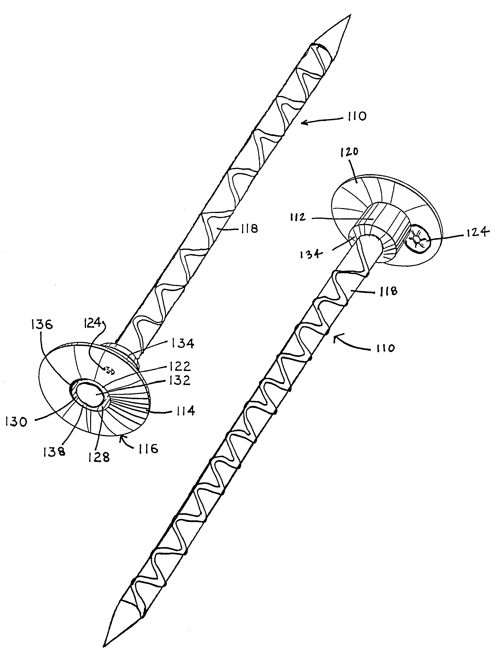
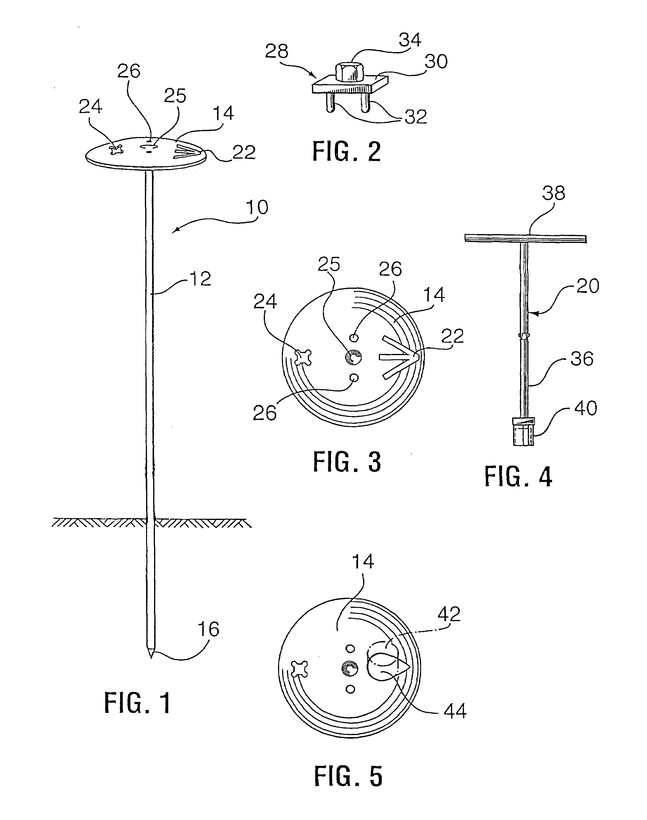
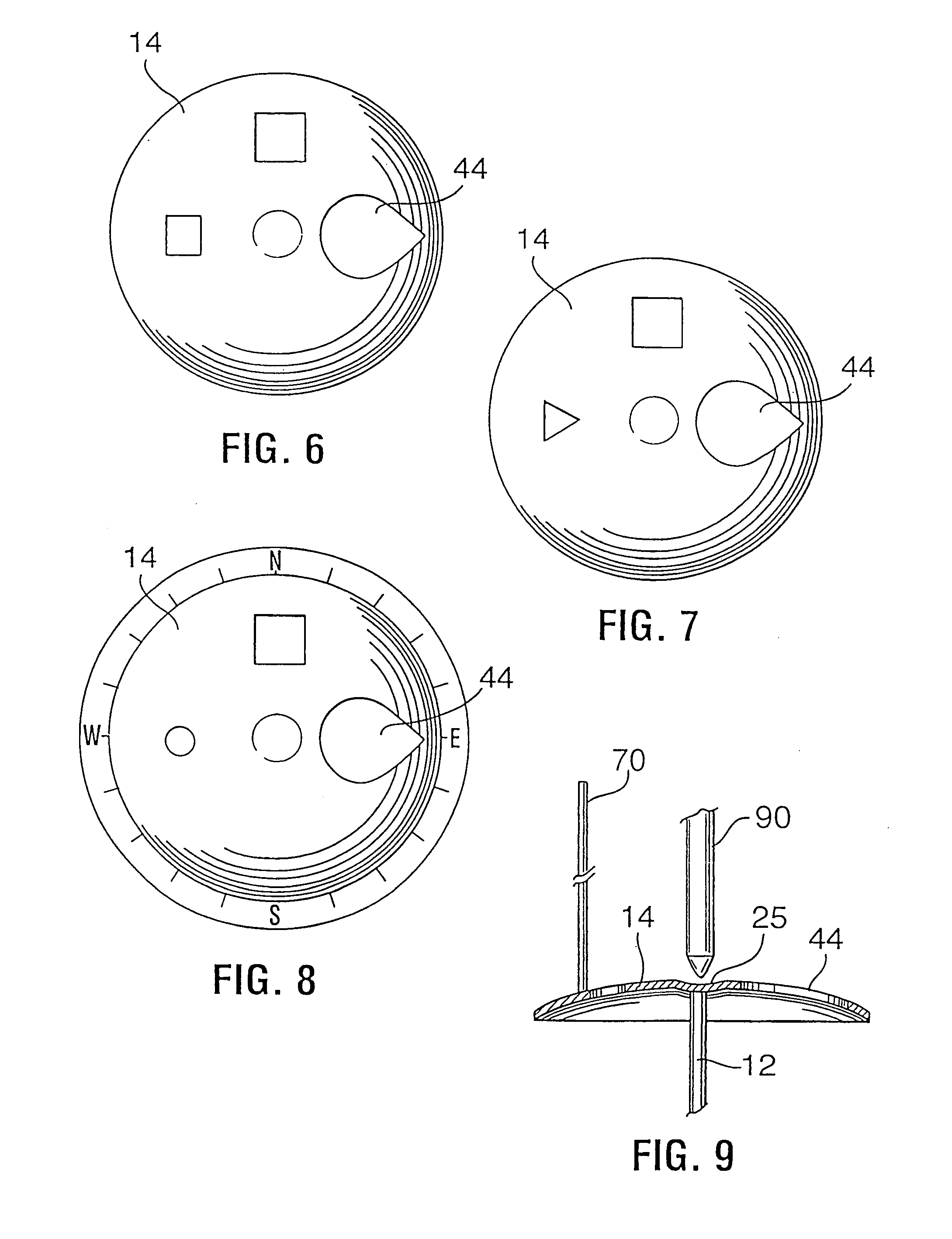
[0042]The survey marker 10 of the present invention as shown in FIG. 1 includes a longitudinal rod 12 for anchoring the survey marker 10 in the earth, and a head portion 14 serving as an indicator source. More particularly, the rod 12 includes a pointed tip 16; however, it is contemplated that a tip having a screw, flat tip, chisel tip, or other cutting edge may be utilized to enhance penetrability of the tip 16 in a hard substrate. The rod 12 of the preferred embodiment is rebar.

[0043]The head 14 attached to the distal end of the rod 12 is generally convex in shape forming a plate having a center point an side edges curving downward therefrom. It is contemplated the head can be formed having a convex top surface and concave bottom surface, or having a convex top surface and flat bottom surface; however, the preferred embodiment is shown in FIG. 1. The head 14 may be a thin metal plate or be solid. Indicia may be printed upon the top surface of the head or on a washer or plate attac...


PUM


Abstract

A survey marker having a rod with a pointed tip and a shank extending therefrom composed of a rod or rebar material. A head extending from a distal end of the rod opposite the point may include means for retaining a survey flag, means for engaging a drive tool, and means for alignment.

Description

CROSS REFERENCE TO RELATED APPLICATIONS[0001]This application claims priority from U.S. Provisional Application Ser. No. 60 / 495,979 filed on Aug. 18, 2003 and U.S. application Ser. No. 10 / 920,702 filed on Aug. 18, 2004 both of which are incorporated by reference herein in their entirety. Reference to documents made in the specification is intended to result in such patents or literature cited are expressly incorporated herein by reference, including any patents or other literature references cited within such documents as if fully set forth in this specification.BACKGROUND OF THE INVENTION[0002]1. Technical Field[0003]The present invention relates to survey markers.[0004]2. Description of the Prior Art[0005]Conventional survey indicators consist of plates, spikes, posts, or rods driven in, placed, or attached to natural geographic structures such as rocks or trees. Most permanent markers are formed of concrete posts or the like utilizing a plate or disk having the requisite markings...

Claims


Application Information

Patent Timeline
Patent Type & Authority Patents(United States)
IPC IPC(8): G01C15/04
CPCG01C15/04
Inventor TRUAX, CLARENCE E.
Owner TRUAX CLARENCE E
Why Eureka
Try Eureka