LED illumination lamp device

a technology of led illumination lamp and supporting member, which is applied in the direction of lighting support device, semiconductor device for light source, lighting and heating apparatus, etc., can solve the problems of limited ability to ensure conventional bulb-type led illumination lamp, and it is necessary to increase either so as to achieve compact size, increase the diameter or the length of the cylindrical supporting member, and sufficient brightness

Inactive Publication Date: 2010-04-06
CITIZEN ELECTRONICS CO LTD
View PDF7 Cites 107 Cited by
  • Summary
  • Abstract
  • Description
  • Claims
  • Application Information

AI Technical Summary

Benefits of technology

[0005]An LED illumination lamp device using a light emitting diode element (hereinafter, referred to as LED element) has the advantageous effects of a lower heat release value, a longer operating life, and so on, in comparison with a conventional illumination lamp without using LED elements such as an electric light bulb. In recent years, LED illumination lamps have been widely used in various circles as illumination lamps for general lighting, headlights for vehicle, or the like. Because one LED element emits only a small volume of light, it has become conventional practice to install a large number of LED elements in one illumination lamp to ensure emission of a large volume of light.
[0006]A known example of an LED illumination lamp is the bulb-type LED illumination lamp in which a large number of LED elements are disposed on a side surface of a cylindrical supporting member to form an electric light bulb (for reference, see Japanese Patent Laid-Open No. 2004-296245, FIG. 1, paragraphs 0014 to 0021, Japanese Patent Laid-Open No. 2004-296249, FIG. 1, paragraphs 0012 to 0019, and Japanese Patent Laid-Open No. 2004-342574, FIGS. 1 to 3, paragraphs 0009 to 0014, and so on).
[0007]However, when installing a large number of LED elements in the above-mentioned conventional bulb-type LED illumination lamp, it has been necessary to increase either the diameter or length of the cylindrical supporting member. Therefore, the conventional bulb-type LED illumination lamp has been limited in its ability to assure bright illumination while maintaining a compact size.SUMMARY OF THE INVENTION
[0008]An object of the present invention is to provide an LED illumination lamp device having sufficient brightness even if it is small in size.
[0009]To accomplish the above object, an LED illumination lamp device according to one embodiment of the present invention includes a polygonal-prism-shaped supporting member having a plurality of rectangular side surfaces, plate-like wing members configured to project outwardly from each of ridge lines formed by two adjacent rectangular side surfaces of the supporting member and having at least two opposing rectangular surfaces, and a plurality of LED elements disposed in three dimensions on the rectangular side surfaces of the supporting member and the rectangular surfaces of the wing members.
[0010]In one embodiment, a plurality of LED elements are assembled in one LED unit. The plurality of LED units are disposed on each of the rectangular side surfaces of the supporting member and the rectangular surfaces of each of the wing members.

Problems solved by technology

However, when installing a large number of LED elements in the above-mentioned conventional bulb-type LED illumination lamp, it has been necessary to increase either the diameter or length of the cylindrical supporting member.
Therefore, the conventional bulb-type LED illumination lamp has been limited in its ability to assure bright illumination while maintaining a compact size.

Method used


Image

  • LED illumination lamp device
  • LED illumination lamp device
  • LED illumination lamp device

Examples


first embodiment

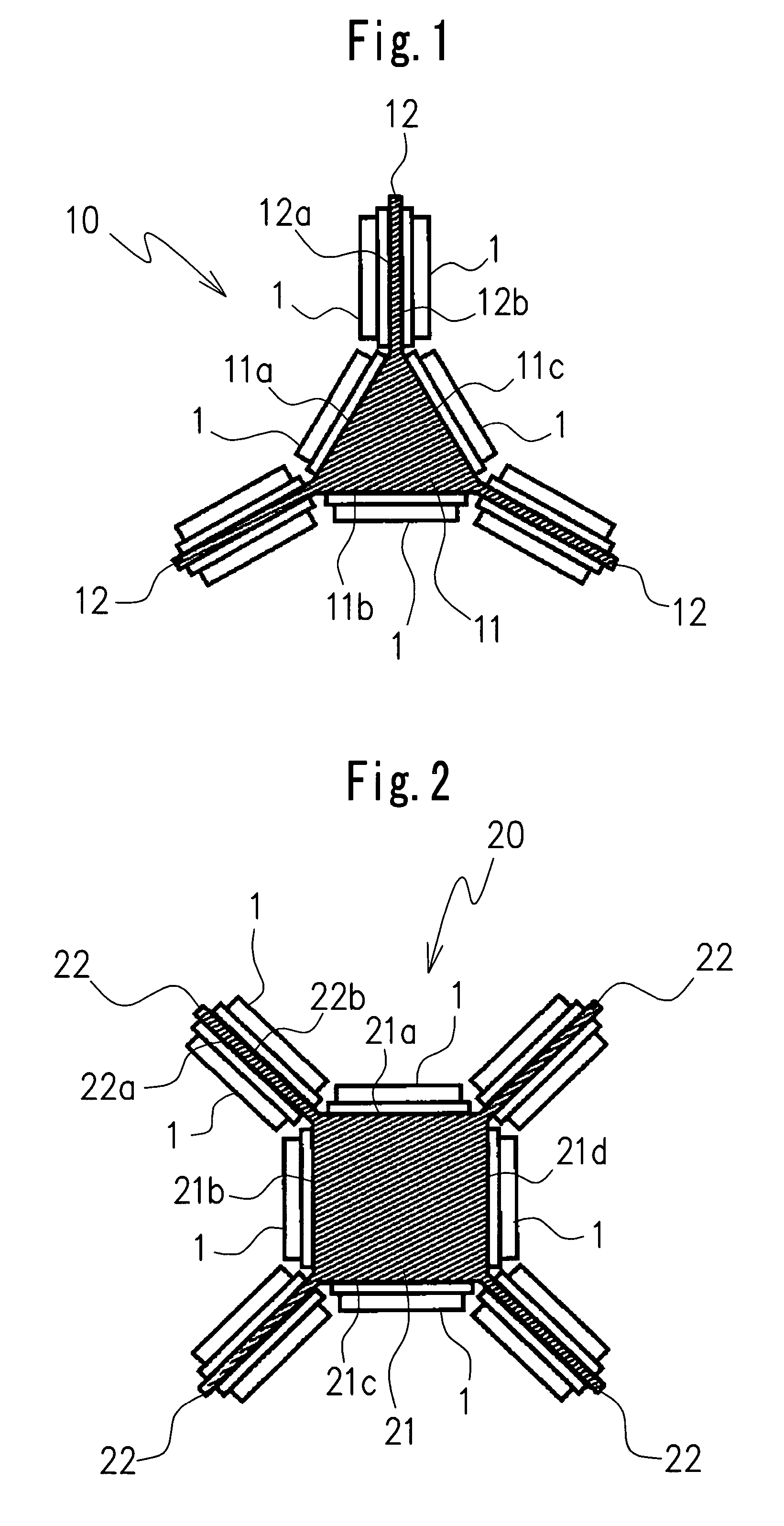
[0024]FIG. 1 illustrates an LED illumination lamp device according to the present invention.

[0025]The first embodiment consists of a bulb-type LED illumination lamp device 10 which contains, for example, a triangular-prism-shaped supporting member 11, three rectangular wing members 12 provided on peripheral ridge lines of the supporting member 11, and a plurality of LED units 1 provided on the supporting member and the wing members 12, as shown in FIG. 1.

[0026]More specifically, the supporting member 11 has rectangular side surfaces 11a to 11c extending to form a triangular prism shape (see FIG. 1). In this embodiment, the supporting member 11 is made of a solid material having a triangular shape in section.

[0027]The three rectangular wing members 12 are provided to project outwardly from ridge lines each of which is formed by adjacent side surfaces of the supporting member 11. Each of the wing members 12 includes two opposing or back-to-back rectangular surfaces 12a and 12b.

[0028]...

second embodiment

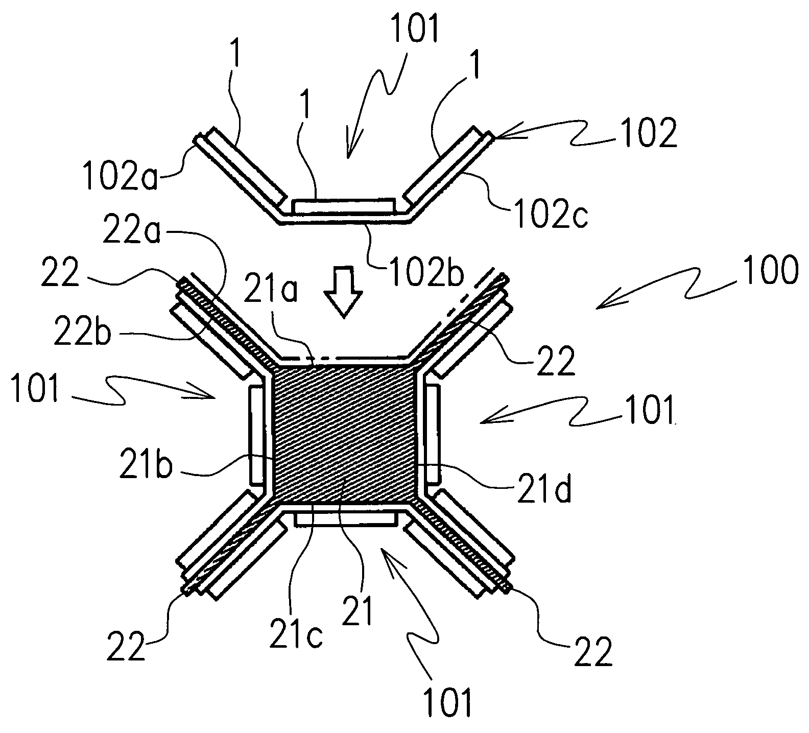
[0039]FIG. 2 illustrates the LED illumination lamp device according to the present invention.

[0040]The LED illumination lamp device 20 in this embodiment is of a bulb type similar to the bulb type as mentioned in the first embodiment. As shown in FIG. 2, the LED illumination lamp device 20 includes a quadrangular-prism-shaped or square-prism-shaped supporting member 21 and four rectangular wing members 22 configured to project from four ridge lines formed by adjacent side surfaces of the supporting member 21. Accordingly, the LED illumination lamp device 20 in the second embodiment is similar in structure to the LED illumination lamp device 10 in the first embodiment, except for the point that the number of LED units 1 disposed on the four side surfaces 21a to 21d of the supporting member 21 and the rectangular surfaces 22a and 22b of each wing member 22 is three more than that in the first embodiment.

[0041]Accordingly, identical reference numbers are attached to parts of the LED il...

third embodiment

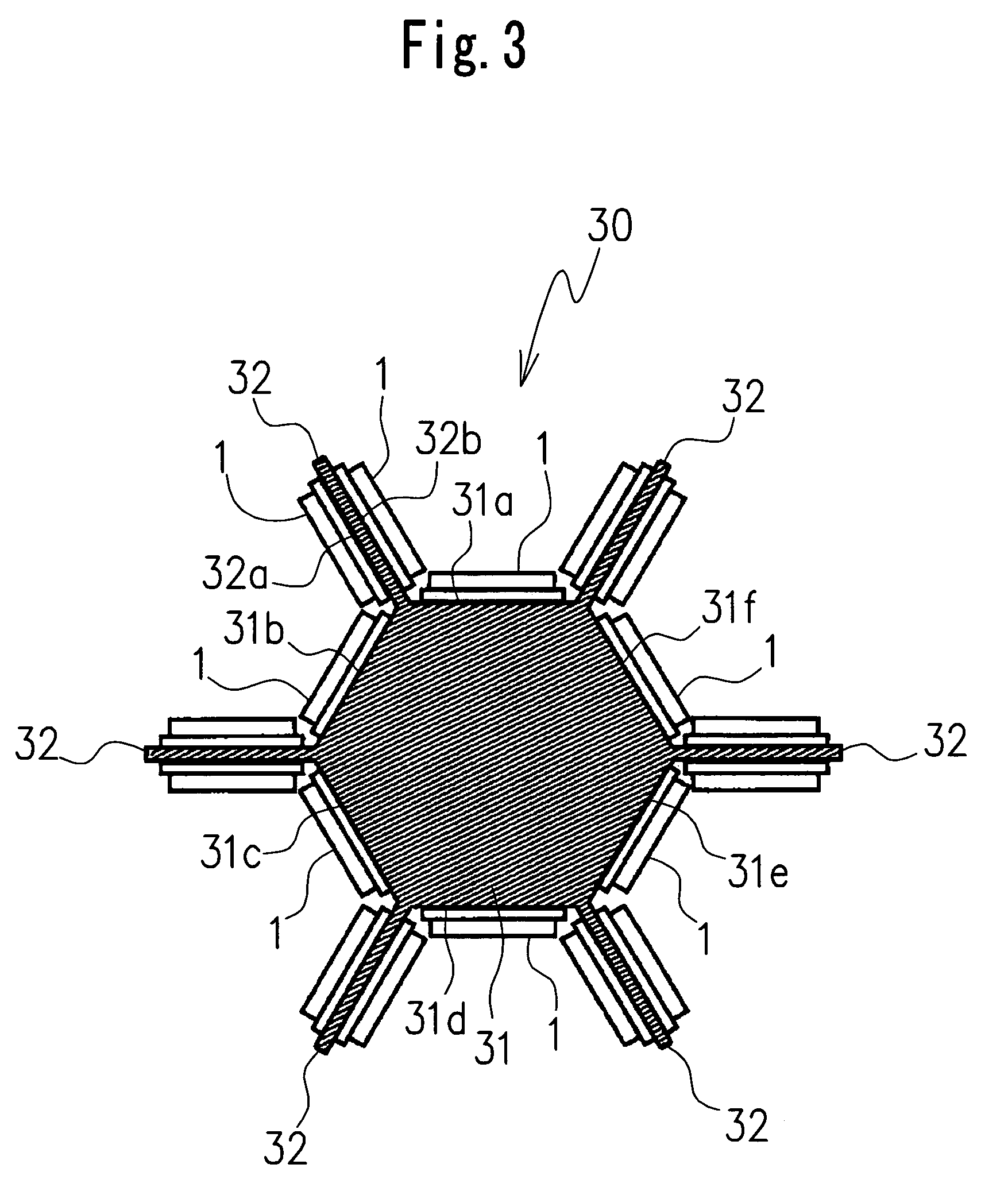
[0042]FIG. 3 illustrates the LED illumination lamp device according to the present invention.

[0043]The LED illumination lamp device 30 in the third embodiment includes a hexagonal-prism-shaped supporting member 31 and six rectangular wing members 32 configured to project from ridge lines formed by adjacent side surfaces of the supporting member 31. Accordingly, the LED illumination lamp device 30 in the third embodiment is similar in structure to the LED illumination lamp device 10 in the first embodiment, except for the point that the number of LED units 1 disposed on the six side surfaces 31a to 31f of the supporting member 31 and the rectangular surfaces 32a and 32b of each wing member 32 can be doubled, compared with the first embodiment.

[0044]Accordingly, identical reference numbers are attached to parts of the LED illumination lamp device 30 similar to those of the LED illumination lamp device 10, and a detailed description of the similar parts is omitted. In addition, the str...


PUM


Abstract

An LED illumination lamp device, including a polygonal-prism-shaped supporting member having a plurality of rectangular side surfaces, plate-like wing members configured to project outwardly from each of ridge lines formed by two adjacent rectangular side surfaces of the supporting member and having at least two opposing rectangular surfaces, and a plurality of LED elements disposed on the rectangular side surfaces of the supporting member and the rectangular surfaces of the wing members.

Description

CROSS-REFERENCE TO THE RELATED APPLICATION[0001]This application is based on and claims priority from Japanese Patent Application No. 2005-133912, filed on May 2, 2005, the disclosure of which is incorporated herein by reference in its entirety.BACKGROUND OF THE INVENTION[0002]1. Field of the Invention[0003]The present invention relates to an LED illumination lamp device for use as an illumination lamp for general lighting, a headlight for vehicle, or the like.[0004]2. Description of Related Art[0005]An LED illumination lamp device using a light emitting diode element (hereinafter, referred to as LED element) has the advantageous effects of a lower heat release value, a longer operating life, and so on, in comparison with a conventional illumination lamp without using LED elements such as an electric light bulb. In recent years, LED illumination lamps have been widely used in various circles as illumination lamps for general lighting, headlights for vehicle, or the like. Because one...

Claims


Application Information

Patent Timeline
Patent Type & Authority Patents(United States)
IPC IPC(8): F21S4/00F21V29/00F21K99/00F21W107/10
CPCF21K9/00F21Y2111/001F21Y2101/02F21K9/60F21Y2107/00F21Y2115/10
Inventor KANAMORI, MASAYOSHIIMAI, SADATO
Owner CITIZEN ELECTRONICS CO LTD
Why Eureka
Try Eureka