Optical pickup

a pickup and optical technology, applied in the field of optical pickups, can solve the problems of limited magnetization surface disposing, difficult to efficiently improve both the sensitivity during the operation in the focusing direction, and the inability to efficiently improve the sensitivity during the operation in the tracking direction. , to achieve the effect of improving both the sensitivity and the sensitivity, reducing the interval of opposition, and increasing the number of magnets used

Inactive Publication Date: 2008-07-08
FUNAI ELECTRIC CO LTD
View PDF10 Cites 0 Cited by
  • Summary
  • Abstract
  • Description
  • Claims
  • Application Information

AI Technical Summary

Benefits of technology

[0011]The invention has been devised in view of the above-described situation, and its object is to provide an optical pickup which is capable of efficiently improving both the sensitivity during the operation in the tracking direction and the sensitivity during the operation in the focusing direction without increasing the number of magnets used.
[0012]Another object of the invention is to provide an optical pickup which is capable of efficiently improving both the sensitivity during the operation in the tracking direction and the sensitivity during the operation in the focusing direction by allowing not only the magnetized surface on one surface side of the magnet but also the magnetized surface on the other surface side to contribute to the formation of magnetic circuits.
[0014]If the above-described construction is provided, a magnetic circuit formed by the focusing coil and the magnetized surface on one surface side of the magnet serves to control the displacement of the lens holder in the focusing direction, while a magnetic circuit formed by the tracking coil and the magnetized surface on the other surface side of the magnet serves to control the displacement of the lens holder in the tracking direction. In addition, the construction adopted is such that each of the magnets is disposed in a space where the focusing coil and the tracking coil are opposed to each other, such that a magnetized surface on one surface side of the magnet is opposed to the focusing coil, and a magnetized surface on the other surface side of the magnet is opposed to the tracking coil. Therefore, since each magnet can be disposed close to both the focusing coil and the tracking coil, it becomes possible to efficiently improve both the sensitivity during the operation in the tracking direction and the sensitivity during the operation in the focusing direction.
[0015]In the invention, it is possible to adopt a construction in which the tracking coils are disposed on both sides between which the focusing coil is disposed, and the magnets are disposed separately in the respective opposition spaces on both sides of the focusing coil. According to this construction, the lens holder can easily be subjected to displacement control in the focusing direction and the tracking direction with a good balance.
[0017]As described above, according to the invention, despite the fact that the arrangement of the magnets, the focusing coil, and the tracking coils is only devised, both magnetized surfaces on one surface side and the other surface side of the magnet contributes to the formation of magnetic circuits for providing displacement control in the focusing direction or the tracking direction. Therefore, it becomes easily possible to reduce the interval of opposition between the magnet and the focusing coil and the interval of opposition between the magnet and the tracking coil more than in a conventional case. For this reason, it becomes possible to provide an optical pickup having an actuator which improves both the sensitivity during the operation in the tracking direction and the sensitivity during the operation in the focusing direction without increasing the number of magnets used. Accordingly, the performance stability of an optical disk apparatus adopting the optical pickup also improves.
[0018]Further, according to the invention, since a magnetic circuit is effectively constituted, an operating current of the focusing coil and that of the tracking coils can be reduced, with the result that a heat release value of the actuator can be reduced.

Problems solved by technology

In this situation, however, it has been difficult to efficiently improve both the sensitivity during the operation in the tracking direction and the sensitivity during the operation in the focusing direction by disposing the magnetized surface of the magnet in close proximity to both the tracking coils and the focusing coil.
Namely, even if the sensitivity during the operation in the tracking direction could be improved by disposing the magnetized surface on one surface side of the magnet close to the tracking coils, since the focusing coil is located on the opposite side to the magnet with the tracking coils disposed therebetween, the tracking coils constitute obstructions, and therefore a limitation occurs to disposing the magnetized surface on one surface side of the magnet close to the focusing coil.
Hence, it has been difficult to efficiently improve both the sensitivity during the operation in the tracking direction and the sensitivity during the operation in the focusing direction.

Method used


Image

  • Optical pickup
  • Optical pickup
  • Optical pickup

Examples


Embodiment Construction

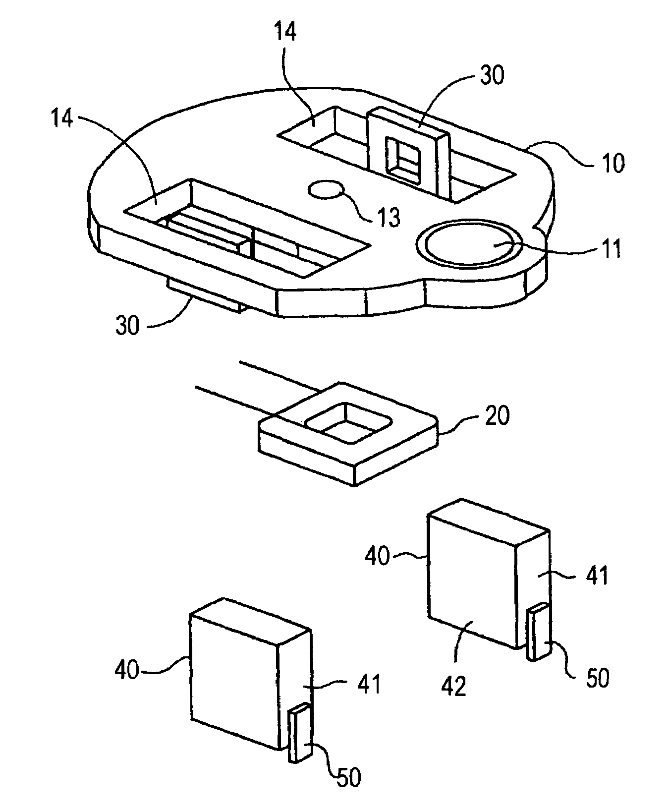
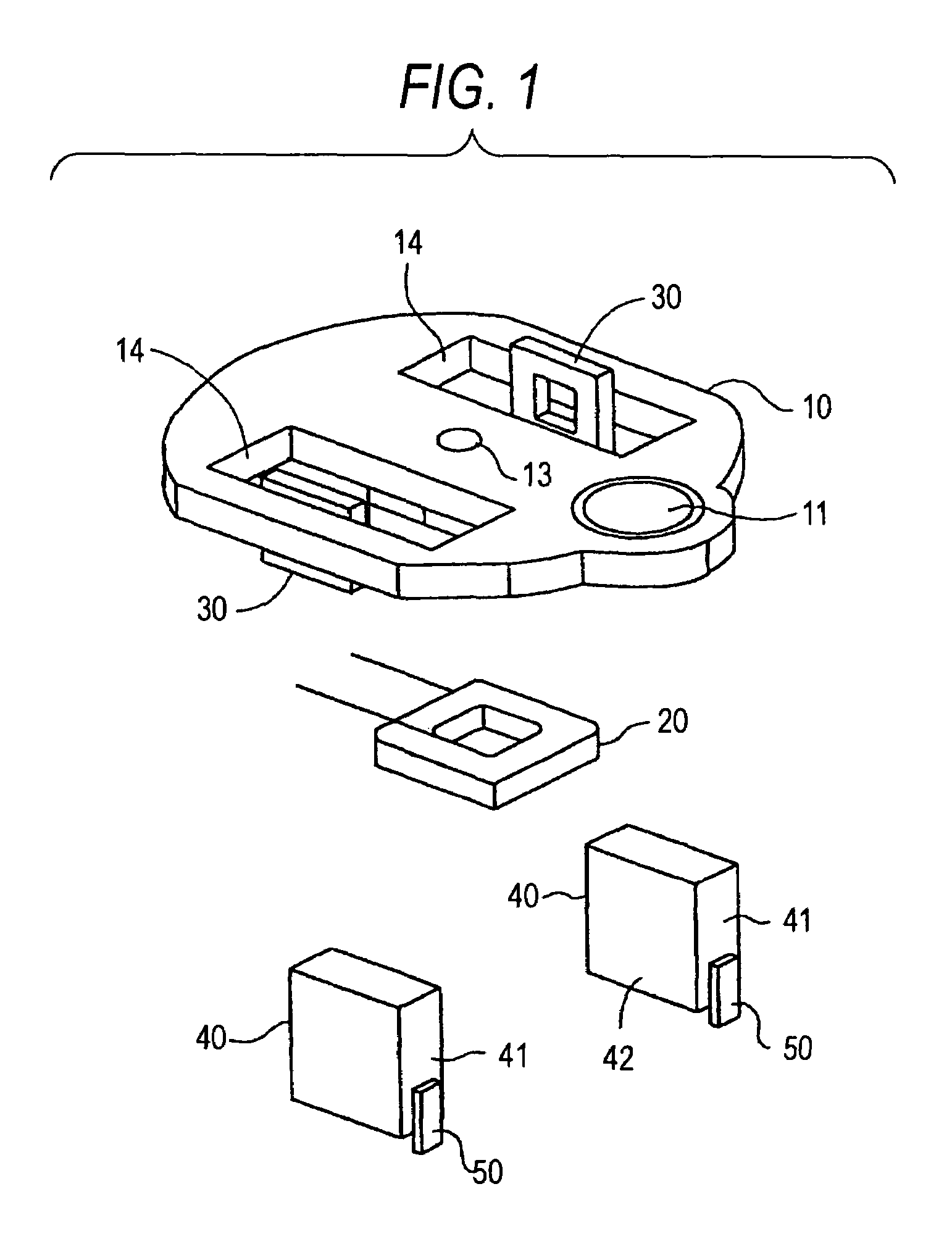
[0024]FIG. 1 is a schematic exploded perspective view of an actuator adopted in the optical pickup in accordance with the invention. FIG. 2 is a schematic plan view of the actuator.

[0025]In FIGS. 1 and 2, reference numeral 10 denotes a lens holder, and an objective lens 11 is provided at is front end portion, while a hole portion 13, into which a supporting shaft 12 secured perpendicularly on a base member (not shown) is fitted, is provided in its central portion. As the supporting shaft 12 is fitted in the hole portion 13, the lens holder 10 is positioned displaceably in a focusing direction and a tracking direction. In addition, a focusing coil 20 is joined to a lower surface of the lens holder 10 in a superposed manner in such a form as to surround the hole portion 13, while a pair of tracking coils 30 are respectively disposed on both left- and right-hand sides between which the focusing coil 20 is disposed. Further, a pair of rectangular through holes 14 are respectively provid...


PUM

PropertyMeasurementUnit
displacementaaaaaaaaaa
stabilityaaaaaaaaaa
shapeaaaaaaaaaa

Abstract

A lens holder is provided with a focusing coil for urging the lens holder in a focusing direction and tracking coils for urging the lens holder in a tracking direction in cooperation with magnets. A magnet is disposed in a space where the focusing coil and the tracking coil are opposed to each other in a through hole of the lens holder, such that a magnetized surface on one surface side of the magnet is opposed to the focusing coil and a magnetized surface on the other surface side thereof is opposed to the tracking coil.

Description

BACKGROUND OF THE INVENTION[0001]1. Field of the Invention[0002]The present invention relates to an optical pickup, and more particularly to an optical pickup including an actuator in which a focusing coil and tracking coils are mounted in a lens holder having an objective lens, and which has magnets for forming magnetic circuits together with the focusing coil and the tracking coils.[0003]2. Description of the Related Art[0004]An optical pickup is used in an optical disk apparatus for effecting recording or reproduction with respect to an optical disk, and a lens holder equipped with an objective lens is mounted on abase member for which access control is provided in a direction along a radial direction of the optical disk. In addition, displacement control is provided for the lens holder in a focusing direction and a tracking direction with respect to the optical disk by the operation of an actuator so as to compensate for a change in the positional relationship between the optica...

Claims


Application Information

Patent Timeline
Patent Type & Authority Patents(United States)
IPC IPC(8): G11B7/00G11B7/12G11B7/09
CPCG11B7/0933G11B7/12G11B7/0935
Inventor NAKAGAWA, RYOTARO
Owner FUNAI ELECTRIC CO LTD
Why Eureka
Try Eureka