Anti-bulging projection screen structure

a projection screen and structure technology, applied in the field of projection screens, can solve the problems of distortion of projected images, damage to the screen surface at the sides, and the surface of the screen will bulge outwardly in the center of the screen,

Inactive Publication Date: 2010-05-04
STEWART FILMSCREEN
View PDF17 Cites 20 Cited by
  • Summary
  • Abstract
  • Description
  • Claims
  • Application Information

AI Technical Summary

Benefits of technology

[0005]The present invention provides an improved projection screen and method of making same wherein a projection screen material of selected size in a generally rectangular shape is formed as by cutting the top edge to the shape of an arc extending from side to side of the material whereby the vertical center dimension (height) of the screen material is shortened relative to the vertical side dimension of the material. Alternatively, the bottom edge can be similarly formed, or both the top and bottom edges can be so formed. With the screen material so formed and tensioned vertically to a generally rectangular mounting frame, the bulging (bellying out) of the screen can be substantially eliminated. In addition, the screen material can be formed to define outwardly curved sides which in the mounted condition further reduces the tendency of the screen material to bulge by relieving side-to-side tension in the mounted screen material.
[0006]The screen material configured according to the invention can be mounted with greater tension, especially in the central regions of the screen, than can be applied to rectangular shaped screen material. In the mounted condition, the top and / or bottom concavity of the screen material together with the increased tension that can be applied causes the screen of the invention to assume the intended substantially rectangular shape with a flatter vertical plane for the projection screen and substantially eliminates the undesirable bulging (or bellying out) of the screen surface in the mounted condition. Eliminating the bulging in the mounted screen is particularly important where movable masking panels are used in conjunction with the projection screen in order to prevent contact between the movable panels and the screen surface.
[0007]The invention represents a significant advancement for home cinema theater applications using fixed, curved wide-screen technology for displaying projected images with improved viewing at wide angles. Combining projector and anamorphic lens technology with the advancement in curved screen technology provided by this invention can result in bright, high-contrast, super-wide, distortion-free image projection for cinema formats filmed in wide formats, such as the 2.35:1 or 2.40:1 aspect ratio format commonly used in theatrical releases, all without the annoying upper or lower black bars framing the projected image that characterize many broadcast formats. The many features of the invention include electronically controlled side masking panels to accommodate other aspect ratios, such as a 16:9 ratio characteristic of television broadcast formats.
[0010]The invention further relates to a method for manufacturing a projection screen structure for home cinema theater applications in displaying an image from a projection source, comprising the steps of: (a) providing a sheet of flexible projection screen material having a projection surface for displaying an image projected thereon; (b) forming said sheet of material to a configuration having top and bottom edges and first and second side edges, at least one of said top and bottom edges having an inwardly curved shape defining a distance at the vertical center of said sheet between said top and bottom edges of said sheet that is smaller than the length of said side edges; (c) providing a generally fixed mounting structure defined by generally parallel inwardly curved top and bottom portions and generally parallel side portions for supporting said sheet of material as a curved projection screen defining an inwardly curved projection surface up to about 12 feet in width; and (d) attaching said sheet of material in a tensioned condition on said mounting structure defining a curved projection surface on said material whereby outward bulging of said material in the mounted condition on said mounting structure is substantially eliminated.

Problems solved by technology

In the mounting of conventional large size flexible projection screen materials, the surface of the screen will bulge outwardly in the center of the screen and on the edges by reason of insufficient tension that can be applied to the screen material to secure the screen in place.
This “bellying out” of the screen surface can occur in either curved or flat surface screens and may result in distortion of the projected image.
Further, if movable masking systems are utilized in conjunction with the screen, the bulging of the screen surface on the vertical sides can interfere with the movement of the masks or otherwise contact the moving masks, which can result in damage to the screen surface at the sides and consequent diminished image quality as well as possible subsequent destruction of the screen itself.

Method used


Image

  • Anti-bulging projection screen structure
  • Anti-bulging projection screen structure
  • Anti-bulging projection screen structure

Examples


Embodiment Construction

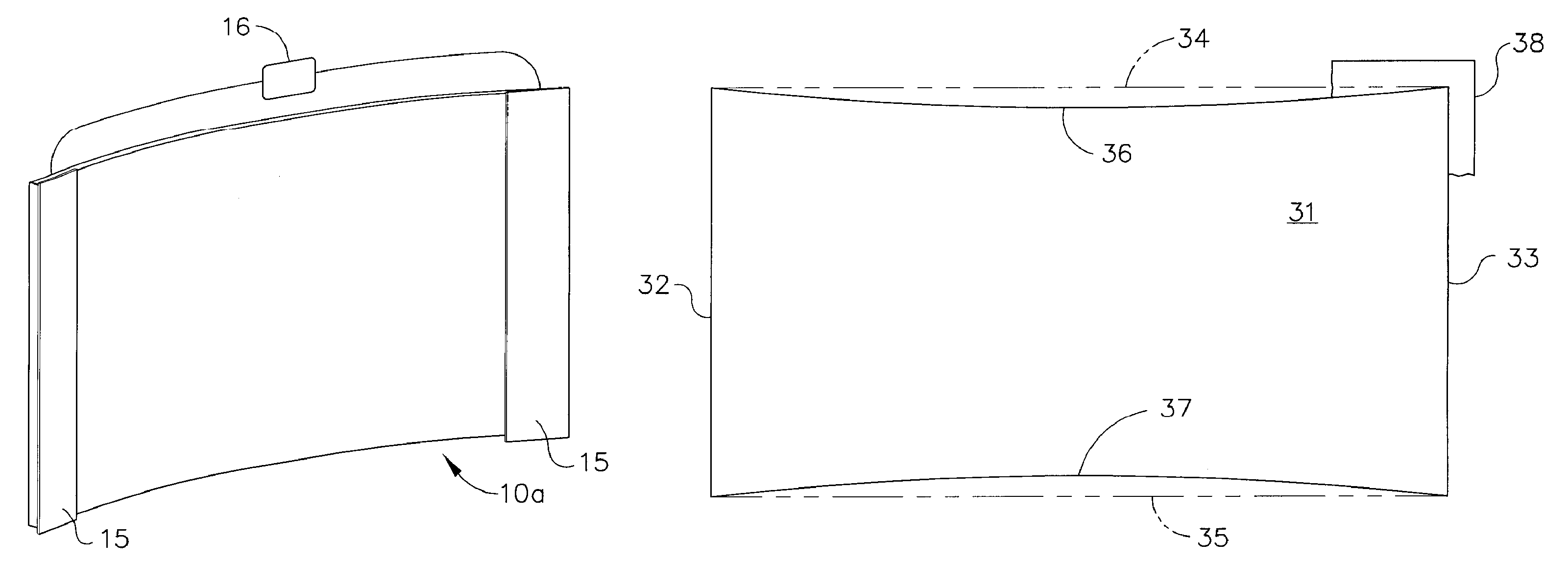
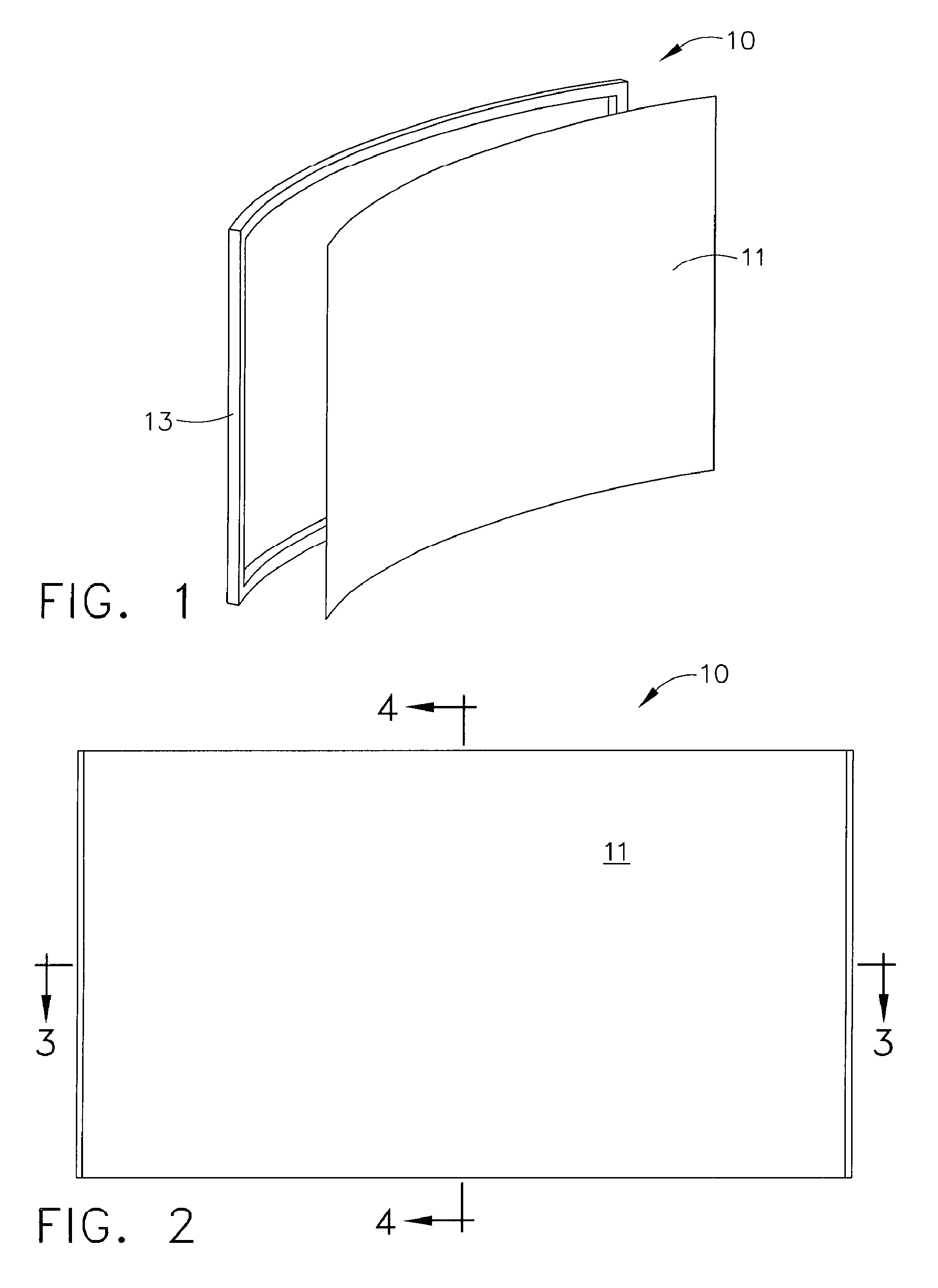
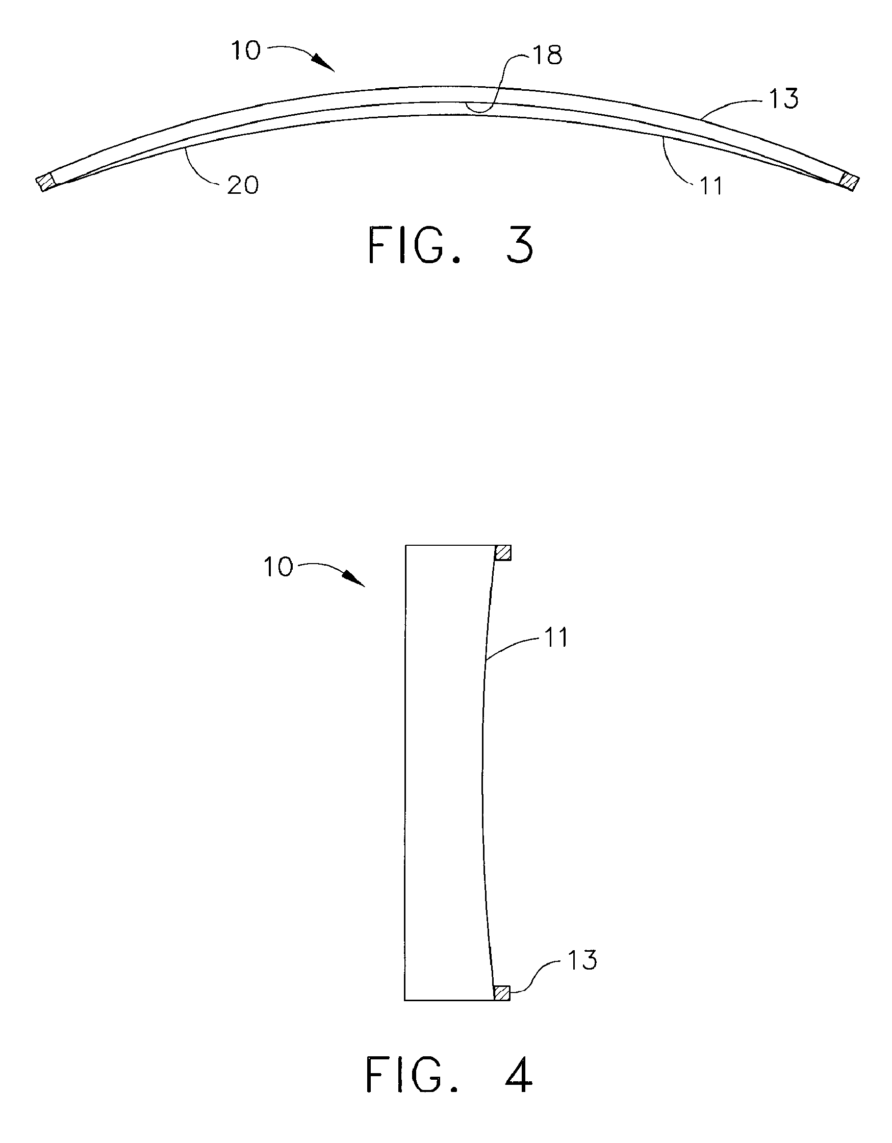
[0024]Referring now to the accompanying drawing figures, FIG. 1 shows a perspective view of a projection screen assembly 10 including a projection screen 11 and mounting structure 13 for supporting screen 11. Screen 11 is shown in FIG. 1 as a curved screen in order to best illustrate the inadequacies of existing screen structures, which inadequacies are addressed by the screen structure described herein. Screen 11 is shown detached from the mounting structure 13 in FIG. 1 to best illustrate the typical curved contour of the screen assembly 10. FIG. 2 is a front view of the screen assembly illustrated in FIG. 1. FIG. 3 and FIG. 4 are sectional views of the FIG. 2 structure respectively taken along line 3-3 and line 4-4. As suggested in FIG. 5, movable side masking panels 15 may be disposed on each side of the screen in order to selectively control the aspect ratio of the projection image area on screen 11. Selective positioning of the masking panels is accomplished using motorized co...


PUM


Abstract

A home cinema theater projection screen structure and method of making same are provided wherein a sheet of projection screen material of selected size is formed to a configuration having concave top and / or bottom edges, the projection screen material then being attached under tension to a mounting structure that defines an inwardly curved projection surface in the mounted condition whereby bulging of the projection surface of the screen is substantially eliminated. Movable side masking panels are included the structure in order to define a selected aspect ratio for the projection surface.

Description

CROSS REFERENCE TO RELATED APPLICATION[0001]This application claims the benefit of co-pending U.S. Provisional Application Ser. No. 60 / 825,348, filed Sep. 12, 2006.FIELD OF INVENTION[0002]The present invention relates generally to projection screens for use in displaying imagery from a TV, motion picture projector, or video projector, or a computer generated images display, or the like, and more particularly to a projection screen structure configured for reducing bulging in the screen surface in the mounted condition.BACKGROUND OF INVENTION[0003]Projection screens of various kinds find substantial use for imagery projection in a large variety of situations for slide or motion picture projection, television or computer generated display, or other imagery projection.[0004]In the mounting of conventional large size flexible projection screen materials, the surface of the screen will bulge outwardly in the center of the screen and on the edges by reason of insufficient tension that can...

Claims


Application Information

Patent Timeline
Patent Type & Authority Patents(United States)
IPC IPC(8): G03B21/56
CPCG03B21/60
Inventor STEWART, PATRICK H.RIVERA, JOAQUIN
Owner STEWART FILMSCREEN
Why Eureka
Try Eureka