Free arm parasol

a free arm and parasol technology, applied in the field of cantilever parasols, can solve the problem that it is now virtually impossible for a person operating the cantilever parasol to be injured when handling, and achieve the effect of further improving the function of the cantilever parasol

Active Publication Date: 2010-05-18
GLATZ AG
View PDF22 Cites 18 Cited by
  • Summary
  • Abstract
  • Description
  • Claims
  • Application Information

AI Technical Summary

Benefits of technology

[0007]Because the locking device has a control rod that is aligned such that it forms an extension to the arm, that may be angled in relation to the carrier element and that may on the one hand be latched to the carrier element and may on the other hand, in the unlatched condition, be pivoted about the axis of the arm and is detachably coupled to the arm by means of a coupling device at selectable angles of rotation in relation to the arm, the functions and settings that are required of the cantilever parasol may be performed simply and easily. The control rod puts the accessibility of the operating members at a smaller height above the ground, with the result that they are accessible even to relatively short people. Moreover, the operating members are located on the outside of the parasol, as a result of which operation is more convenient and more secure against accidents. Because of the lever arm formed by the control rod, it is also simpler and easier to pivot the arm about its axis. Because the control rod serves on the one hand to pivot the arm about its axis and on the other to lock the pivot position by latching the control rod to the carrier element, operation is made substantially simpler and can moreover be performed with one hand. However, the control rod also serves to extend and retract the arm along its axis, as a result of which this function of the cantilever parasol is made simpler and easier.
[0008]A particularly advantageous embodiment is where the bearing for the end of the arm is arranged in a housing on which on the one hand the carrier element is articulated and on the other hand a housing part that carries the control rod is mounted such that it may pivot about the axis of the arm, and in which the coupling device is arranged. As a result, the sensitive parts of the cantilever parasol are arranged in a housing, which on the one hand protects the sensitive parts from soiling and on the other also serves to provide functional reliability and protection from accidents. It is thus now virtually impossible for a person operating the parasol to be injured when handling it.
[0011]To avoid malfunction of the cantilever parasol, it is advantageous if the pivot angle of the arm is preferably limited by stops.
[0012]Functioning of the cantilever parasol is furthermore substantially improved by constructing the cantilever parasol such that the arm and the control rod are constructed to be hollow for the purpose of guiding a tensor member for opening and closing the parasol. In this case, the embodiment is particularly advantageous, in accordance with which a cable winder for the tensor member is provided at the free end of the control rod, by means of which the parasol can be opened and closed.
[0013]Locking of the control rod on the carrier element is performed, preferably by means of a clip, as a result of which the control rod is on the one hand locked quickly and simply and on the other hand the locking can be released again just as quickly and simply.
[0014]To prevent the arm from being extended unintentionally, the further development of the cantilever parasol is advantageous. Here, the arm may be latched in its extended position by means of a latch that can be released by hand again by means of a release member. The cantilever parasol having the extendable and retractable arm and the simple, combined operating elements does not only make it possible to operate the cantilever parasol simply and easily, but also, finally, makes it possible to fold it together in a manner suitable for transportation to give a compact, slender package, which is shortened such that in particular it may even be transported by car.

Problems solved by technology

It is thus now virtually impossible for a person operating the parasol to be injured when handling it.

Method used


Image

  • Free arm parasol
  • Free arm parasol
  • Free arm parasol

Examples


Embodiment Construction

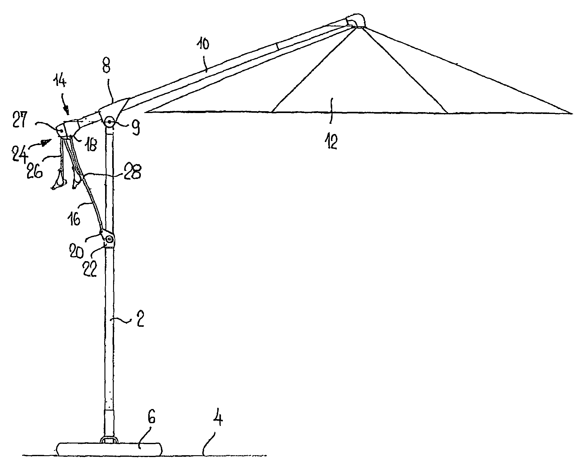
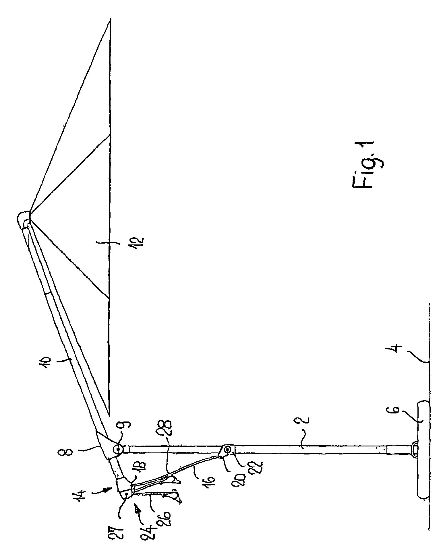
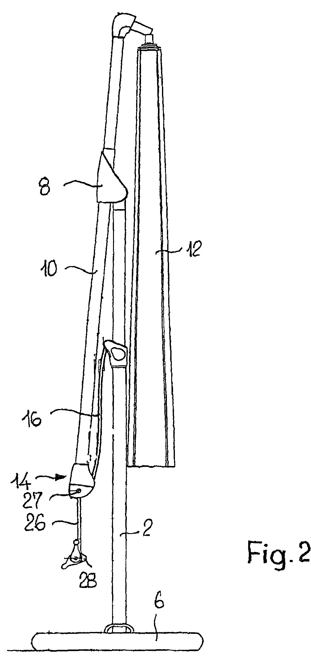
[0027]FIG. 1 shows a cantilever parasol in its extended position, with the parasol open, and FIG. 2 shows this cantilever parasol in the closed, folded-up position. The cantilever parasol has a mast 2, which may be anchored in the ground 4 or in a base 6. At the upper end of the mast 2, on a sliding bearing 8, an arm 10 is mounted such that it may be extended and retracted in its longitudinal direction and such that it may pivot about its axis. The sliding bearing 8 is arranged on the mast 2 such that it may pivot by way of an articulation means 9. At one end the arm carries a parasol 12 and at the other end the arm 10 is mounted in a bearing 14 such that it may pivot about its axis. The bearing 14 is supported against the mast 2 by way of a carrier element 16. To this end, the carrier element 16 is secured to the bearing 14 by way of an articulation means 18 and to a carrier sleeve 22, which is arranged on the mast 2, by way of an articulation means 20. There is a locking device 24...


PUM


Abstract

The invention relates to a free arm parasol which comprises a pole (2) whereon an extension arm (10) is guided such that it can be extended and detracted in the direction of the axis thereof, and can pivoted about the axis thereof. The extension arm (10) supports a parasol (12) on the end thereof and is rotationally mounted on the other end in a bearing (14). A carrier element (16), which is connected in an articulated manner to the pole (2), is connected to bearing. Also, a stopping device (24), which is used to stop the pivotable positioning of the extension arm (10), is provided on the bearing (14). Said stopping device comprises a steering bar (26) which is arranged in the extension of the extension arm (10), can be placed counter to the carrier element (16), can be locked to the carrier element (16) and can be pivoted about the axis of the extension arm (10) when in the unlocked state in order to improve the handling of the free arm parasol. Said arm is coupled in a detachable manner to the extension arm by means of a coupling device, according to a selected rotational angle in relation to the extension arm (10).

Description

[0001]This application claims priority of PCT application PCT / CH2006 / 000368 having a priority date of Aug. 25, 2005, disclosure of which is incorporated herein by reference.TECHNICAL FIELD[0002]The invention relates to a cantilever parasol.BACKGROUND OF THE INVENTION[0003]A cantilever parasol of the type mentioned at the outset is known from EP 0 830 074 B. A split bearing ring of the bearing serves as a locking device, and on the one side the end of the arm is arranged to be rotatable thereon and on the other the carrier element is articulated thereto, this carrier element in turn being supported in articulated manner on the mast. For the purpose of locking, the bearing ring may be tensioned to the arm by means of a clamping screw. A handle that projects transversely to the arm serves to pivot the arm about its axis. It is disadvantageous that both the handle and the clamping screw are arranged relatively high up above the ground and so accessibility and handling is made more diffi...

Claims


Application Information

Patent Timeline
Patent Type & Authority Patents(United States)
IPC IPC(8): A45B23/00A45B17/00
CPCA45B23/00A45B25/14A45B25/24A45B2025/146A45B2023/0037A45B2023/0081A45B2023/0012
Inventor GLATZ, ADOLF
Owner GLATZ AG
Why Eureka
Try Eureka