
Post and railing assembly with support bracket covers

a technology of bracket covers and posts, applied in the direction of balustrades, building types, constructions, etc., can solve the problems of termites, prolonged rotting, and deterioration of timber over time, and achieve the effect of railings, prolonging the life of timber, and reducing the number of posts

Active Publication Date: 2010-06-08
BARRETTE OUTDOOR LIVING INC
View PDF108 Cites 25 Cited by
  • Summary
  • Abstract
  • Description
  • Claims
  • Application Information

AI Technical Summary

Benefits of technology

The invention is a method and assembly for installing a post and railing system. The technical effects of the invention include providing a simple and easy-to-use method for installing a post and railing assembly, as well as a trim cover that securely attaches to the bracket and railing end, ensuring stability and durability. Additionally, the invention includes a U-shaped bracket that allows for flexibility in the installation of the railing, and a trim cover that provides a secure and visually appealing appearance.

Problems solved by technology

Although timber is a reasonably sturdy material, timber wears down over time, yielding to extreme weather conditions, prolonged rotting, termite infestation, and other factors.
Even treated timber can experience rotting and warping.
Although plastic railing materials are more durable than timber in many respects, known plastic railing systems have some drawbacks.
For example, some plastic systems include a large number of fasteners and parts that make installation difficult and costly.
In addition, many plastic railing systems have visible flaws that detract from the overall visual impression of the finished assembly and reflect a low standard of workmanship.
A problem with conventional covers is that they too require visible fasteners to connect them to the assembly.
Covers that require fasteners increase the number of small parts to be handled in the field, which in turn, increases installation time and labor.
Therefore, conventional attempts to improve the appearance of post and railing systems leave much to be desired.

Method used


Image

  • Post and railing assembly with support bracket covers
  • Post and railing assembly with support bracket covers
  • Post and railing assembly with support bracket covers

Examples


Embodiment Construction

[0059]Although the invention is illustrated and described herein with reference to specific embodiments, the invention is not intended to be limited to the details shown. Rather, various modifications may be made in the details within the scope and range of equivalents of the claims and without departing from the invention.

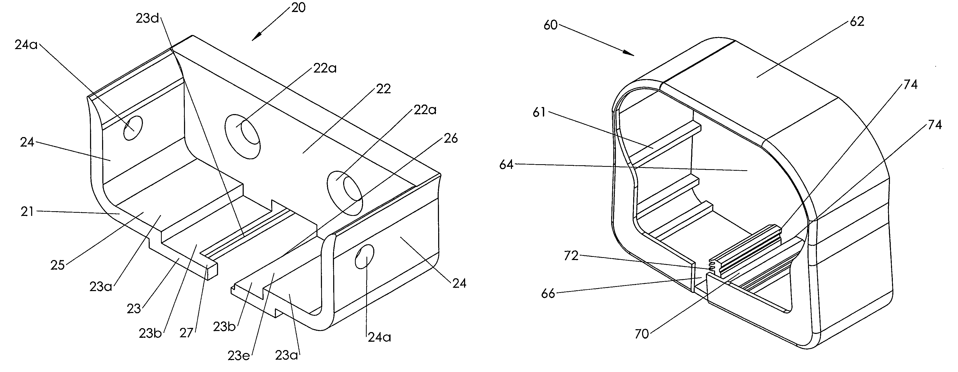
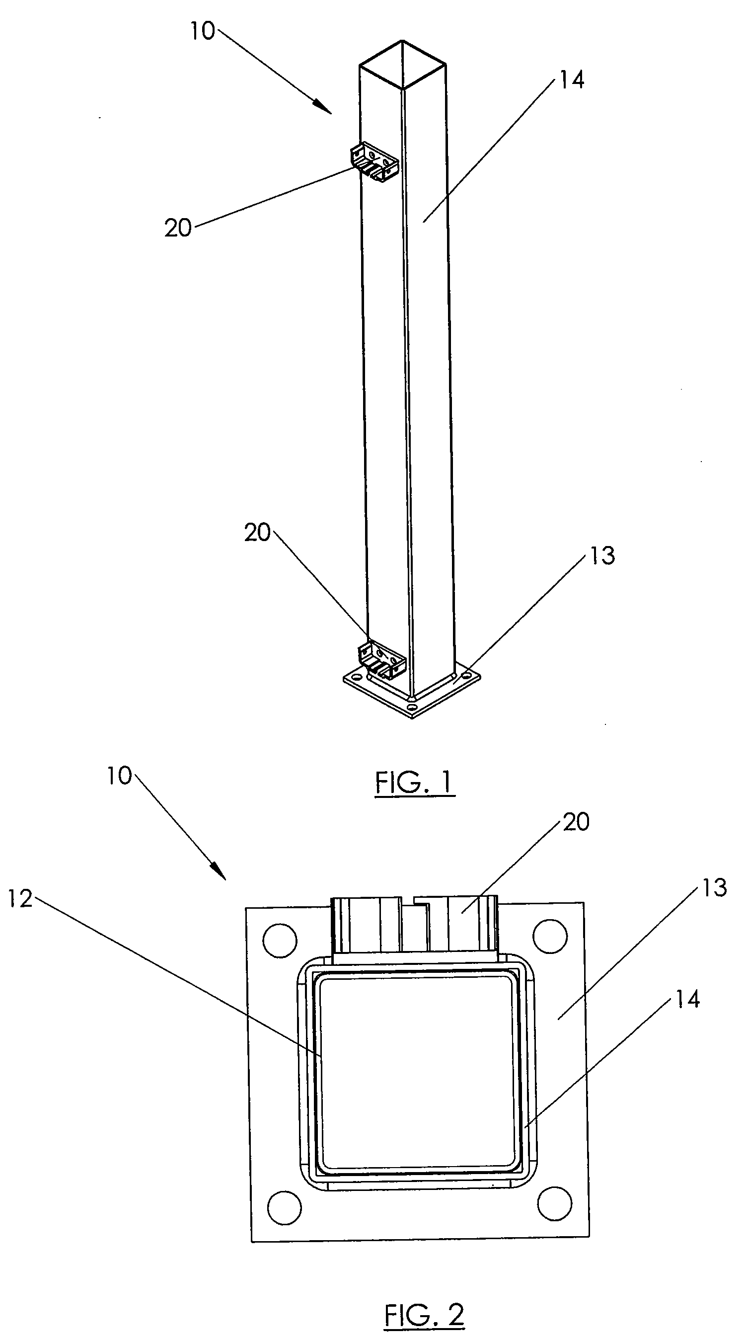
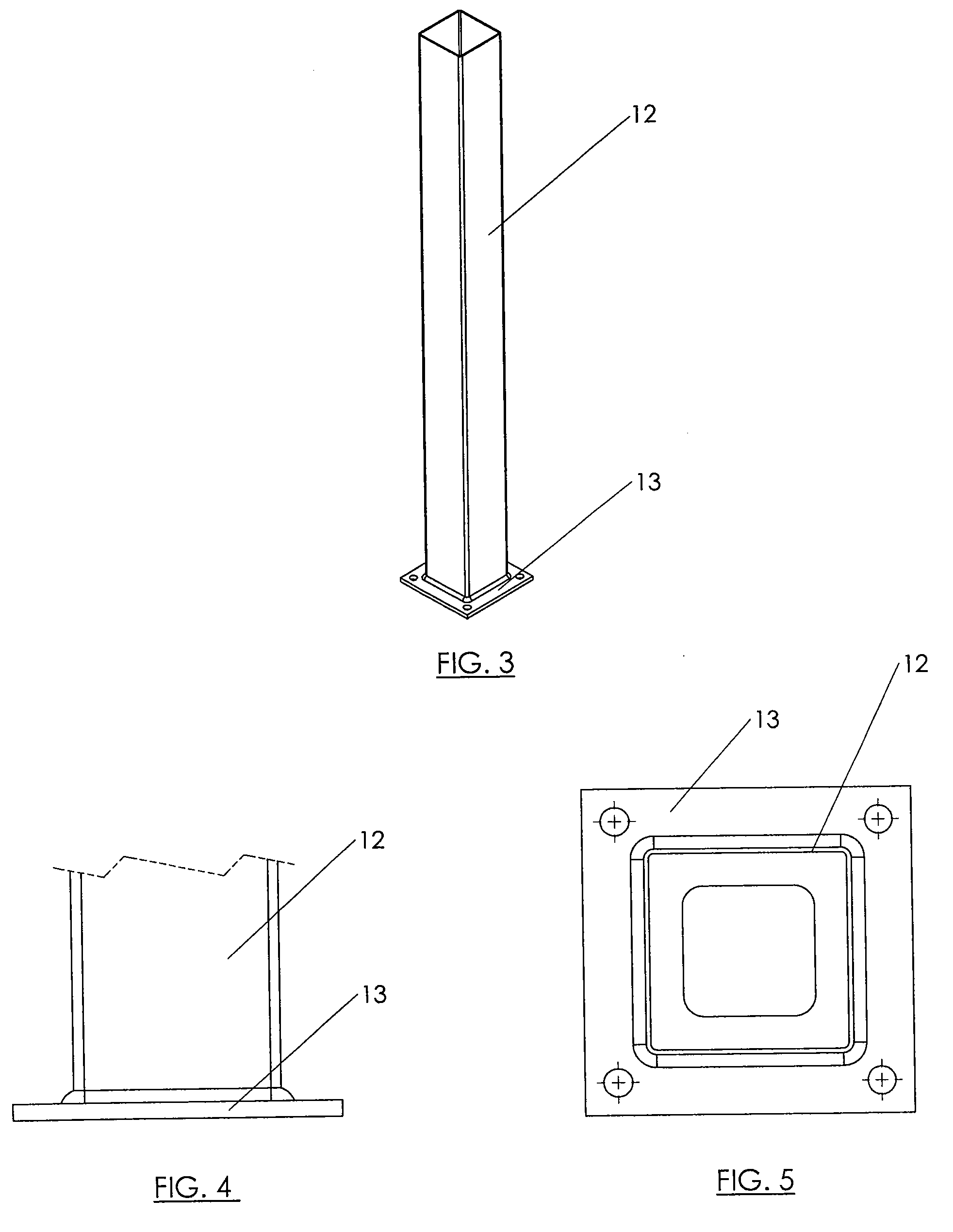
[0060]A post and railing assembly in accordance with the invention is manufactured and sold in pre-assembled units, allowing manual assembly in the field with the use of a minimal number of fasteners and tools. The assembly includes a pre-assembled post with pre-mounted support brackets. During installation, a pair of the pre-assembled posts are mounted in place, and a pre-assembled railing span is connected between the posts using the pre-mounted brackets. Rails on the railing span are secured in the brackets by fasteners. The brackets are then concealed by applying a cover trim around the mounted railing. The cover trims are secured to the underside of the mount...


PUM


Abstract

A railing mounting assembly includes a U-shaped bracket having a pair of sidewalls and a bottom wall, the bottom wall comprising a pair of platform portions for supporting a railing, and a pair of recessed portions separated from one another by a channel, and a trim cover attached around the bracket, the trim cover having a slit and at least one locking member projecting through the channel of the U-shaped bracket.

Description

RELATED APPLICATIONS[0001]This application claims the benefit under 35 U.S.C. §119 of U.S. Provisional Application Ser. No. 60 / 995,911, filed Sep. 28, 2007, the contents of which are hereby incorporated by reference in their entirety for all purposes.FIELD OF THE INVENTION[0002]The present invention relates generally to post and railing systems, and more specifically to components and methods for mounting railings to support structures.BACKGROUND[0003]Post and railing systems, such as guard rail systems for decks and porches, have traditionally been constructed using a variety of timber, including pine and cedar. Although timber is a reasonably sturdy material, timber wears down over time, yielding to extreme weather conditions, prolonged rotting, termite infestation, and other factors. Even treated timber can experience rotting and warping. The development of polyvinylchloride (PVC) and other plastics has led to the use of plastics in post and railing assemblies. Although plastic r...

Claims


Application Information

Patent Timeline
Patent Type & Authority Patents(United States)
IPC IPC(8): E04H17/00
CPCE04F11/1836E04F2011/1897E04F11/1814
Inventor TERRELS, CHRISTOPHER J.SCHNIEDER, CHRISTOPHER MICHAELWERNER, JASON MICHAEL
Owner BARRETTE OUTDOOR LIVING INC
Learn More