Reverse energy bow

a bow and energy technology, applied in the field of shooting bows, can solve the problems of increasing the difficulty of accurate aiming and the attempt to shorten the compound bow

Inactive Publication Date: 2010-06-29
WOODLAND DENNIS R
View PDF11 Cites 54 Cited by
  • Summary
  • Abstract
  • Description
  • Claims
  • Application Information

AI Technical Summary

Problems solved by technology

However, attempts to shorten compound bows have been met with problems because reducing the bow length tends to reduce power while amplifying certain forces acting on and within the bow that may make accurate aiming more difficult.

Method used


Image

  • Reverse energy bow
  • Reverse energy bow
  • Reverse energy bow

Examples


Embodiment Construction

[0014]The following detailed description of the invention is merely exemplary in nature and is not intended to limit the invention or the applications and uses of the invention. Furthermore, there is no intention to be bound by any theory presented in the preceding background of the invention or the following detailed description of the invention.

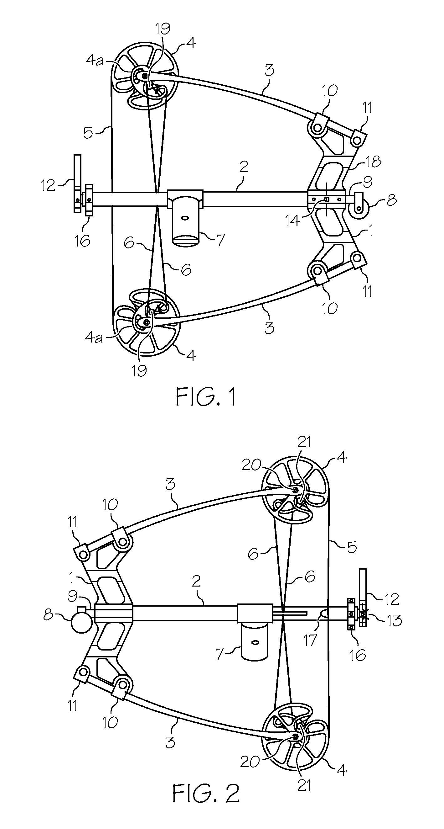
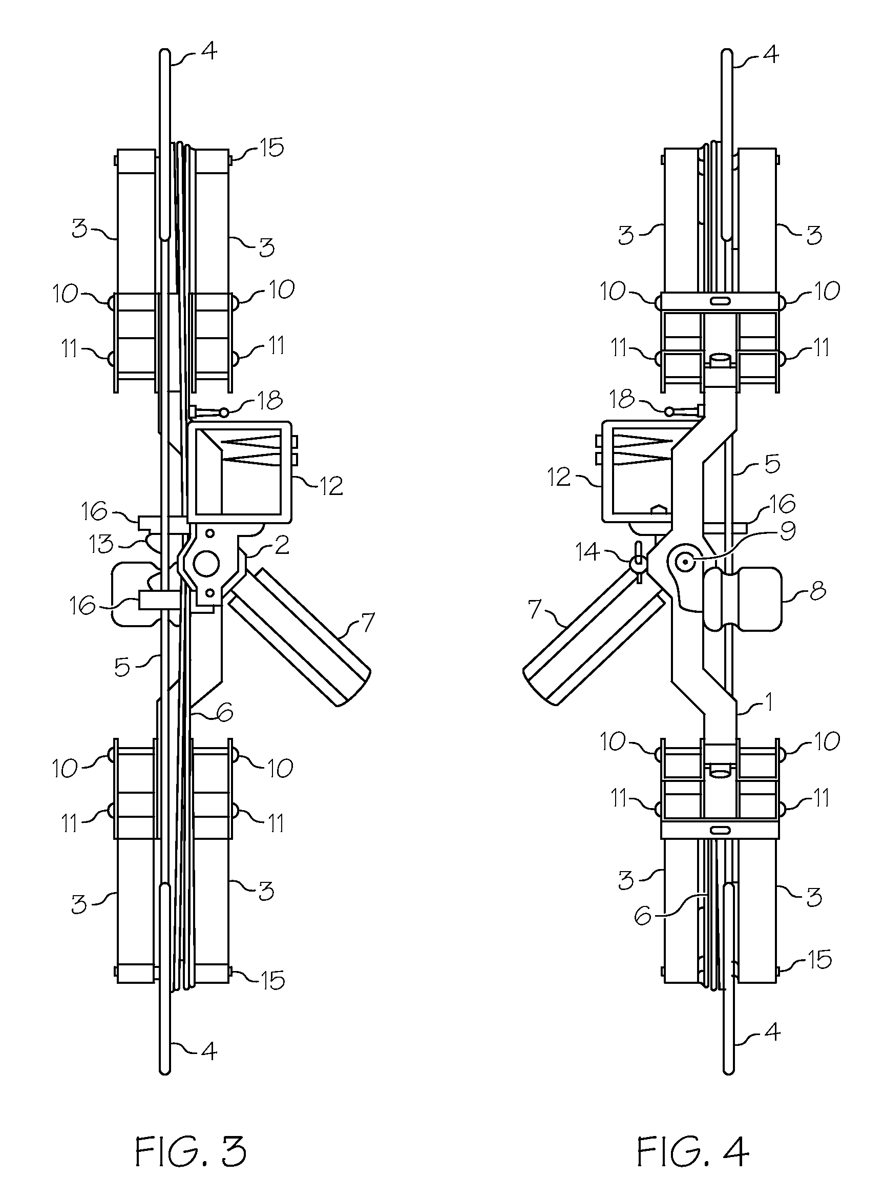
[0015]Turning now to FIGS. 1 to 4, an exemplary compound shooting bow is depicted according to an embodiment of the invention. While describing the bow 100, the term “forward” refers to the direction along the bow headed away from an archer operating the bow 100, and the term “rearward” refers to the direction along the bow headed toward the archer operating the bow 100. The bow 100 includes a main riser frame 1 that supports an elongate tube 2, and four limbs 3 that extend forwardly from the main riser frame 1. Each of the limbs 3 is attached approximate their rearward ends to the main riser frame 1 using a limb rocker retainer 11 and a li...


PUM


Abstract

An archery bow includes a main riser frame with limbs extending therefrom. Each of the limbs has forward ends extended from the main riser frame. A bowstring has wound ends that are wound onto each of wheel cams that are attached to the limbs. The bowstring has a middle section that is not wound onto the wheel cams and that begins and ends at points on the wheel cams that are proximate to the farthest points along the wheel cams from the main riser frame. An elongate tube is mounted to the main riser frame through the central bore, and has a front handle attached to the elongate tube outer surface, and positioned between the first and second pairs of limbs. A push rod is slidably mounted at least partially inside the elongate tube, and has a rearward handle disposed outside the elongate tube rearward end.

Description

CROSS-REFERENCES TO RELATED APPLICATIONS[0001]This application claims the benefit of U.S. Provisional Application No. 60 / 619,828, filed Oct. 18, 2004.FIELD OF THE INVENTION[0002]The present invention generally relates to shooting bows, and more particularly relates to hand-drawn, hand-held shooting bows designed for hunting and sport shooting.BACKGROUND OF THE INVENTION[0003]Archery bows have been known for centuries. Compound bows are a relatively recent development. The early compound bows included an eccentric wheel or cam, which provided a lesser pull weight (or let-off) at full draw than the maximum weight applied at an intermediate draw position. Thus, the compound bow stores a substantial amount of energy without requiring the archer to hold the maximum draw weight while aiming or waiting for a clear shot opportunity.[0004]The technology of compound bows has evolved, including attempts to reduce the overall bow length. A short length makes carrying and handling the bow less c...

Claims


Application Information

Patent Timeline
Patent Type & Authority Patents(United States)
IPC IPC(8): F41B5/10F41B5/12
CPCF41B5/0094F41B5/1469F41B5/10
Inventor WOODLAND, DENNIS R.
Owner WOODLAND DENNIS R
Why Eureka
Try Eureka