
Baby stroller frame with seat direction changing mechanism

a technology of seat direction and stroller frame, which is applied in the direction of hand carts, understructures, loading-carrying vehicle superstructures, etc., can solve the problems of inconvenient steering and still aris

Inactive Publication Date: 2010-07-13
LINK TREASURE
View PDF7 Cites 40 Cited by
  • Summary
  • Abstract
  • Description
  • Claims
  • Application Information

AI Technical Summary

Benefits of technology

[0007]In order to fulfill the above object, the present invention provides a baby stroller frame with a swivelable seat. The user can change the swivelable seat direction by rotating the push bar to an upright position and thereafter to fix the handle bar to the rear wheel side, so as to accommodate the baby sitting and facing the care giver and this would also permit the care giver to steer the baby stroller normally.
[0009]The swivelable seat has a pair of push bars connected to the sides thereof through a pair of lockable swivel base, wherein the lockable swivel base can be used to lock and unlock the push bars that permits the push bars to be fixed either forwardly or backwardly. The swivelable seat may further comprise a driving mechanism driven by the push bars for unlocking the locking mechanism so as to permit the swivelable connector to be rotatable relative to the collapsible wheeled frame thereby to change the direction of the swivelable seat.

Problems solved by technology

Although Huang's stroller has provided the good idea and convenience for care givers to change the handle bar direction for comforting a crying baby without having to stop and see, an inconvenience is still arisen while the user is needed to change the handle bars direction in a narrow or tiny space; for instance, to operate the rotation of the handle bar in a crowded elevator.
Further, when the handle bar is rotated and fixed at the front wheel side would cause a difficult steering, because an ordinary rear wheel sets are direction-fixed, and the front wheel sets are normally be swivelable for easy steering and making to turn around.

Method used


Image

  • Baby stroller frame with seat direction changing mechanism
  • Baby stroller frame with seat direction changing mechanism
  • Baby stroller frame with seat direction changing mechanism

Examples


Embodiment Construction

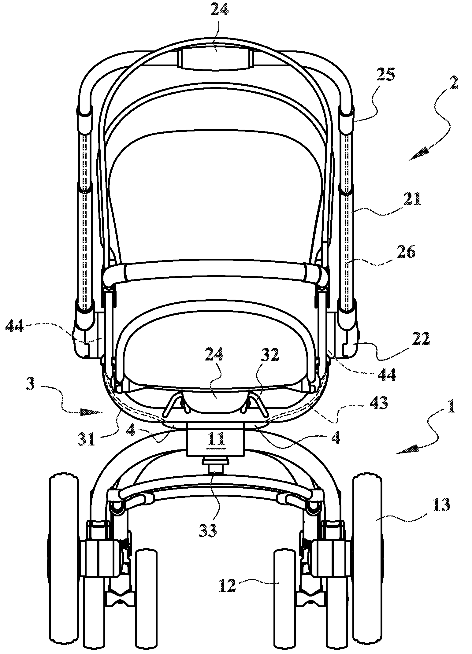
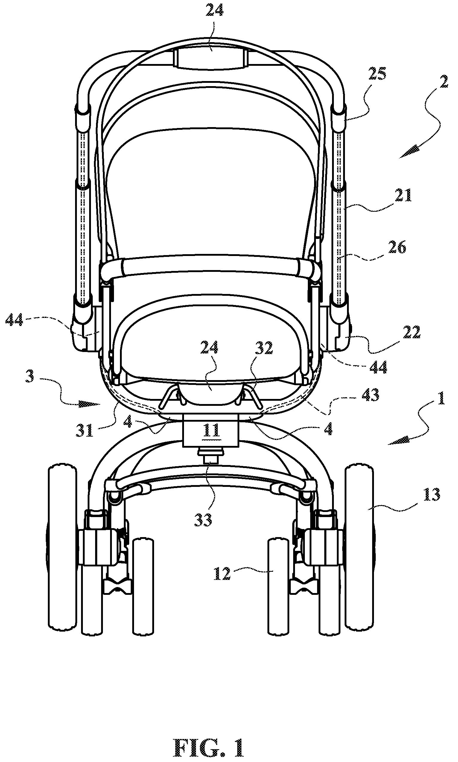
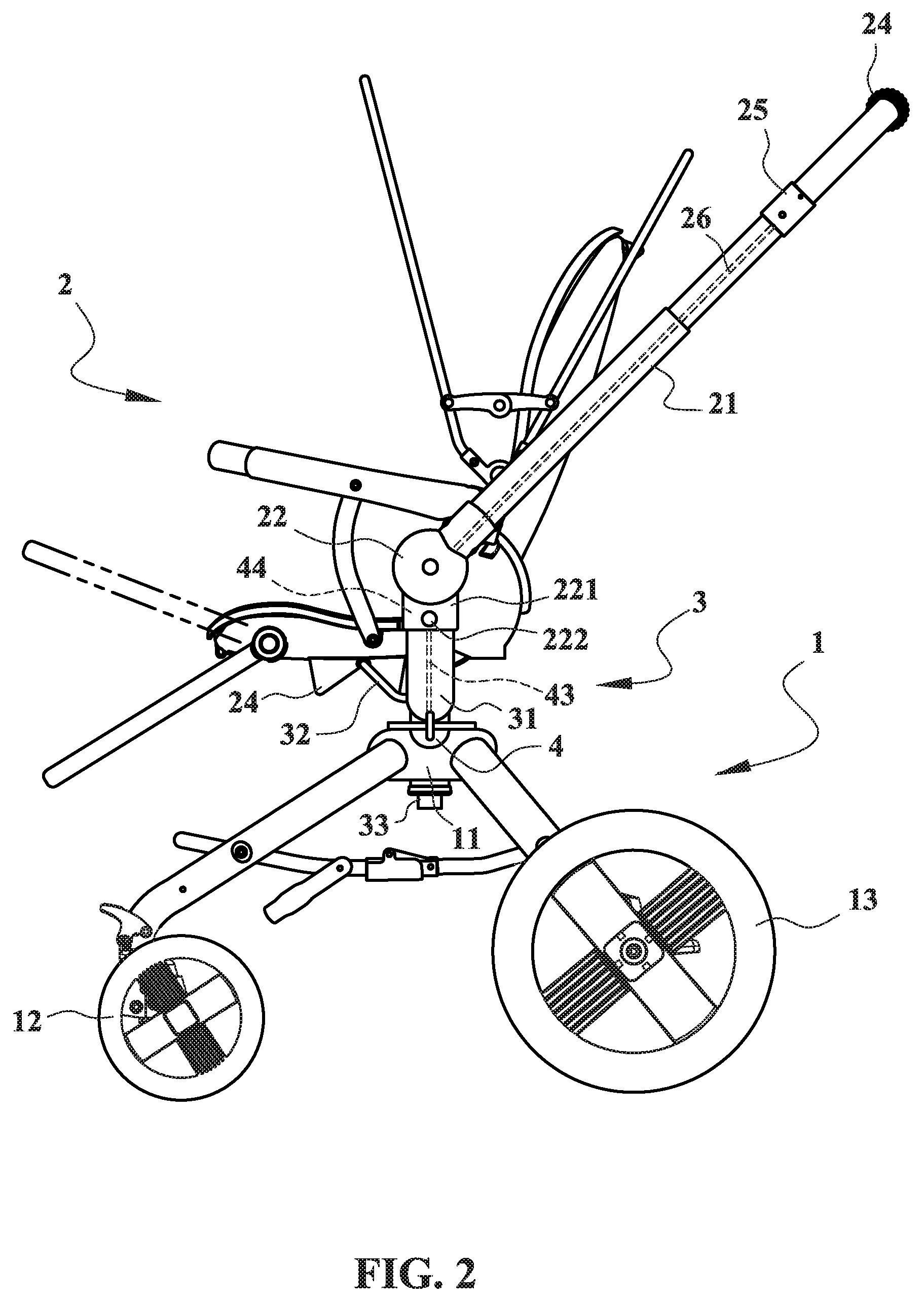
[0024]With referring to FIGS. 1 and 2, an embodiment of a baby stroller frame according to the present invention comprises a collapsible wheeled frame 1, a swivelable seat 2, and a swivelable connector 3.

[0025]The swivelable connector 3 is connected between the collapsible wheeled frame 1 and the swivelable seat 2 and pivotally connected atop the collapsible wheeled frame 1 and comprises at least a locking mechanism 4 for fixing the swivelable connector 3 in a plurality of predetermined directions.

[0026]The swivelable connector 3 is swively mounted atop the swiveling mount 11 and comprises a locking mechanism 4 for releasably engaging with the locking position 110, so as to lock the swivelable connector 3 in a fixed direction.

[0027]The collapsible wheeled frame 1 comprises at least a swiveling mount 11, at least a front wheel 12 and a pair of rear wheels 13. The front wheel 12 may have a castoring axle for facilitating the steering to turn around, and the rear wheels 13 may have a b...


PUM


Abstract

A baby stroller comprises a collapsible wheeled frame, a swivelable seat, and a swivelable connector connected between the collapsible wheeled frame and the swivelable seat. The swivelable connector is pivotally connected atop the collapsible wheeled frame and has a locking mechanism for fixing the swivelable connector in a plurality of predetermined directions. The swivelable seat has a pair of push bars connected to both sides thereof through a pair of lockable swivel base, wherein the lockable swivel base can be used to lock the push bars either forwardly or backwardly and comprises a driving mechanism for unlocking the locking mechanism so as to permit the swivelable connector to rotate relative to the collapsible wheeled frame 1 thereby to change the direction of the swivelable seat.

Description

CROSS REFERENCE TO RELATED APPLICATIONS[0001]This invention is a continuation-in-part of U.S. Ser. No. 11 / 509,704, filed Aug. 25, 2006, entitled “BABY STROLLER FRAME WITH SEAT DIRECTION CHANGING MECHANISM”. The disclosure of the above identified co-pending application is incorporated herein by reference in its entirety.FIELD OF THE INVENTION[0002]The present invention relates to a baby stroller frame with a swivelable seat, and more particularly, to a baby stroller frame which can be operative to change the seat direction thereof by rotating a pair of push bars connected on either sides of the seat, and the push bars can be restored to the rear wheels side for pushing baby stroller.DESCRIPTION OF THE RELATED ART[0003]Baby stroller is provided for baby or small children that can be pushed by a care giver for traveling forwardly together. Normally, the seat and handle bar of traditional baby stroller are fixed in a non-changeable direction, that makes a baby can only sit and face forw...

Claims


Application Information

Patent Timeline
Patent Type & Authority Patents(United States)
IPC IPC(8): B62B1/00
CPCB62B9/102B62B7/142B62B9/203B62B2203/071B62B7/062
Inventor YANG, CHENG-FAN
Owner LINK TREASURE
Learn More