Mounting assembly with adjustable spring tension

a technology of mounting assembly and adjustable spring tension, which is applied in the direction of mechanical equipment, manufacturing tools, and rod connections, etc. it can solve the problems of affecting the installation of the cam foot, the cam foot rotation can damage the rail, and the space on the upper receiver rail b>12/b> is limited, so as to prevent the loosening of the nut once installed, prevent over-tightening, and reliably moun

Inactive Publication Date: 2010-07-20
SWAN RICHARD E
View PDF27 Cites 28 Cited by
  • Summary
  • Abstract
  • Description
  • Claims
  • Application Information

AI Technical Summary

Benefits of technology

[0016]To insure that the retention nut remains in the position set by the user, actuator arm includes a spring-biased indexing pin that engages indexing formations on the outer surface of the retention nut. The indexing formations correspond to different levels of preset tension, i.e. tight, medium and loose. It is this adjustment in the initial spring tension that directly translates to the amount of force with which the clamping assembly engages the rail. Should the user wish to adjust the spring tension, the retention nut is turned until the desired spring tension is achieved. The retention nut also includes mechanical stop that prevents over tightening as well as a shoulder that prevents loosening of the nut once installed.
[0017]Accordingly, it is an object of the present invention to provide an improved mounting assembly that allows for the releasable mounting of various accessories onto the standard dovetail rail found on modern combat weapons. Further, it is an object of the present invention to provide a mounting assembly that can be reliably mounted onto a dovetail rail while including an actuator that includes the ability to adjust the spring tension that is exerted by the clamping foot. It is still a further object of the present invention to provide a mounting assembly having an adjustable actuator that further includes indexed presets that allow a user to predictably and reliably control the spring tension and clamping force of the mounting assembly while also preventing accidental over tightening thereof.

Problems solved by technology

However, space on the upper receiver rail 12 is limited, and many military personnel often have multiple sighting devices that are each tailored to perform in different combat situations.
The difficulty is that there is simply not enough space on the integrated rail provided on the upper receiver to accommodate all of the desired accessories.
Similarly, if the camming force is too great, rotation of the cam foot can damage the rail.
Finally, despite the benefits of a fixed, self-adjusting range of spring tension provided by the prior art device, in certain environments, there is still a perceived need to adjust the range of the spring tension, for example if rails have excessive wear there may be a need to slightly increase the initial spring tension.
Tighter is not better in these circumstances and overtightening can lead to damage to the rail of the weapon.

Method used


Image

  • Mounting assembly with adjustable spring tension
  • Mounting assembly with adjustable spring tension
  • Mounting assembly with adjustable spring tension

Examples


Embodiment Construction

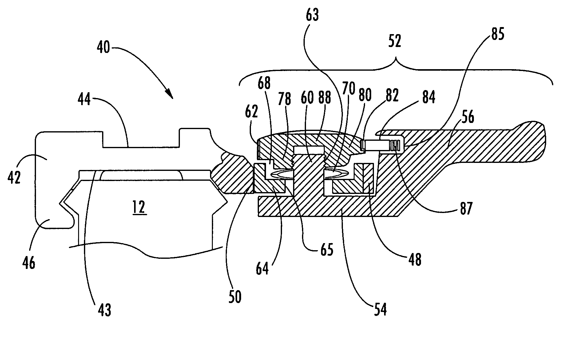
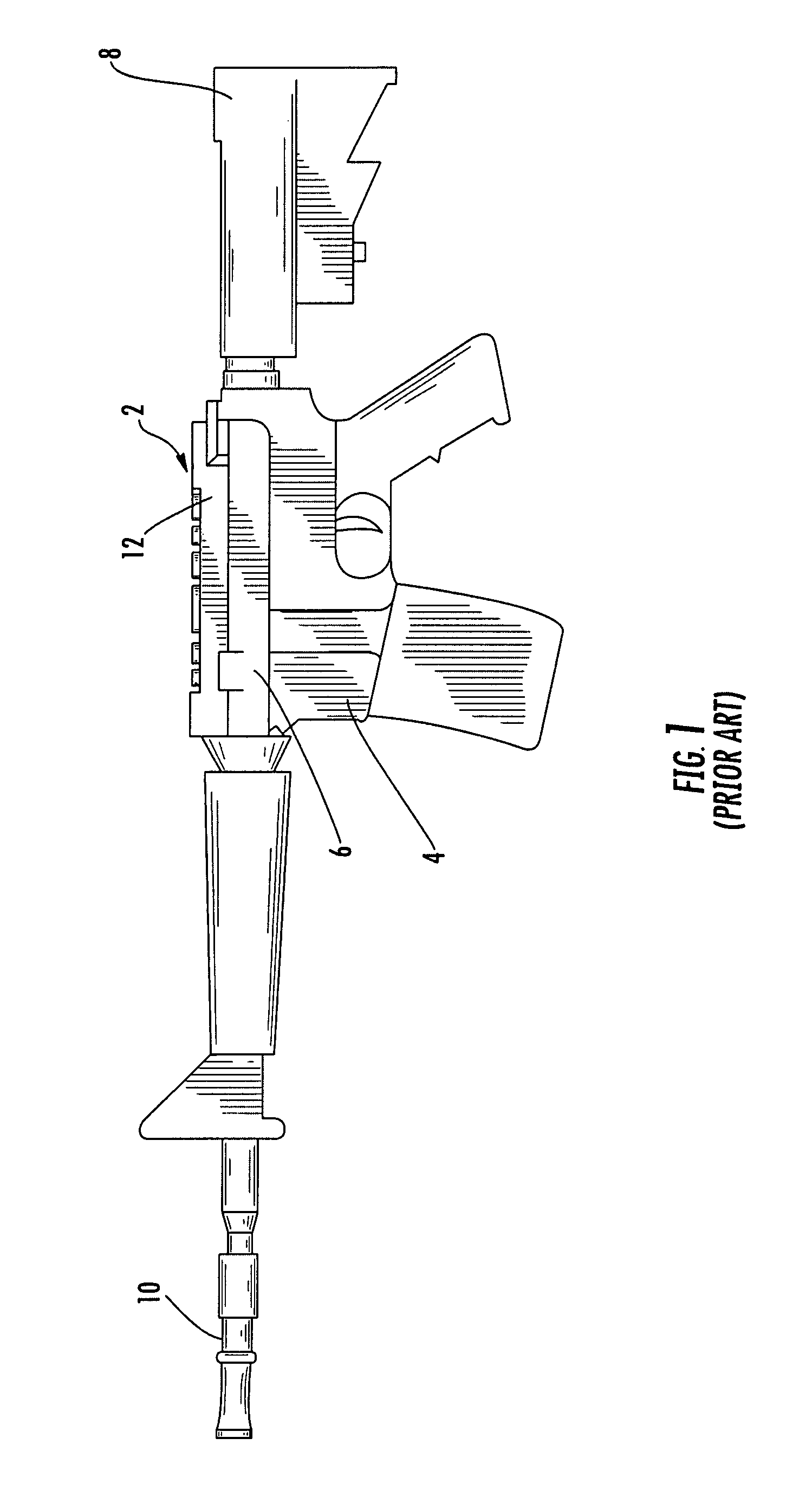
[0027]Now referring to the drawings, the mounting assembly is shown and generally illustrated at 40 in FIGS. 4-6. The mounting assembly 40 is configured to be releasably attached to a standard dovetail rail profile 12 as is depicted in FIG. 1, and includes a means for adjustment to control the clamping force exerted by the mounting assembly 40 against the dovetail rail 12, as will be discussed in more detail below. The mounting assembly 40 of the present invention is particularly suited for use in connection with any firearm 2 that utilizes a standard dovetail rail 12 or a supplemental rail system.

[0028]Turning now to FIG. 4, as can be seen, the mounting assembly 40 includes a main body 42 that is configured in substantially the same manner as a traditional prior art device and further includes a lower portion 43 that is configured to engage the dovetail rail 12 found on most modern combat weapons 2 and an upper portion 44 that can take on a variety of configurations depending on th...


PUM


Abstract

An improved mounting assembly is provided that is configured to be releasably attached to a standard dovetail rail profile, wherein the initial clamping tension of the clamping actuator is adjustable. The mounting assembly generally includes a main body having a lower portion that is configured to engage a standard dovetail and an upper portion accessory receiving formation. The lower portion of the mounting assembly has a first engagement member extending downwardly along one side thereof for engaging one side of the dovetail rail and a clamping assembly to engage the opposing side of the dovetail rail. At least one spring and a retention nut are provided as part of the clamping assembly such that retention nut controls the preset spring tension thereby controlling the clamping force applied by the clamping assembly.

Description

CROSS-REFERENCE TO RELATED APPLICATIONS[0001]This application is related to and claims priority from earlier filed U.S. Provisional Patent Application No. 60 / 864,022, filed Nov. 2, 2006.BACKGROUND OF THE INVENTION[0002]The present invention relates generally to modular integrated accessory mounting assemblies for combat weapons. More specifically, the present invention relates to an accessory mounting assembly, which includes an actuator that is incorporated into the accessory mount in a manner that provides adjustable spring tension to control the clamping force exerted by the actuator against the firearm interface rail.[0003]As the field of combat and commercial weaponry expands, numerous add-on enhancements have become available for attachment to standard firearms, thereby significantly upgrading the capability of the firearm. Of particular interest in the area of combat weapons is the well-known M16 / M4 weapon system (M16 and M4 are trademarks of Colt Defense, Inc.). The M16 has ...

Claims


Application Information

Patent Timeline
Patent Type & Authority Patents(United States)
IPC IPC(8): F41G1/38
CPCF41C23/16F41G11/003Y10T403/7071
Inventor SWAN, RICHARD E.
Owner SWAN RICHARD E
Why Eureka
Try Eureka