Mounting assembly with adjustable spring tension

a technology of mounting assembly and spring tension, which is applied in the direction of mechanical equipment, manufacturing tools, and rod connections, etc., can solve the problems of affecting the service life of the upper receiver, and simply not enough space on the upper receiver's integrated rail to accommodate all of the desired accessories, etc., to achieve reliable spring tension control and reliable mounting

Active Publication Date: 2010-07-20
SWAN RICHARD E
View PDF26 Cites 35 Cited by
  • Summary
  • Abstract
  • Description
  • Claims
  • Application Information

AI Technical Summary

Benefits of technology

[0022]Accordingly, it is an object of the present invention to provide an improved mounting assembly that allows for the releasable mounting of various accessories onto the standard dovetail rail found on modern combat weapons. Further, it is an object of the present invention to provide a mounting assembly that can be reliably mounted onto a dovetail rail while including

Problems solved by technology

However, space on the upper receiver rail 12 is limited, and many military personnel often have multiple sighting devices that are each tailored to perform in different combat situations.
The difficulty is that there is simply not enough space on the integrated rail provided on the upper receiver to accommodate all of the desired accessories.
Similarly, if the camming force is too great, rotation of the cam foot can damage the rail creating a slopp

Method used


Image

  • Mounting assembly with adjustable spring tension
  • Mounting assembly with adjustable spring tension
  • Mounting assembly with adjustable spring tension

Examples


second embodiment

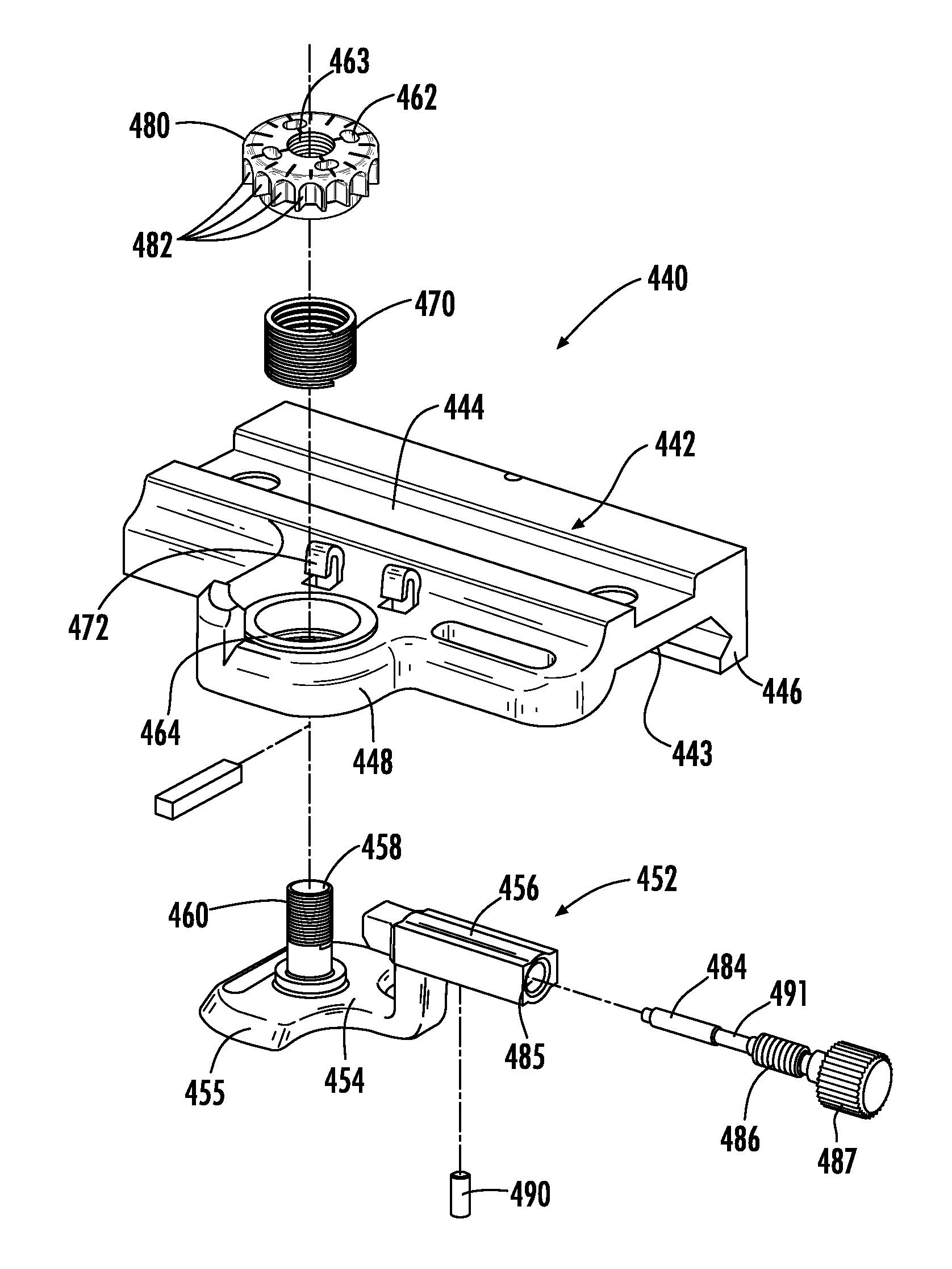
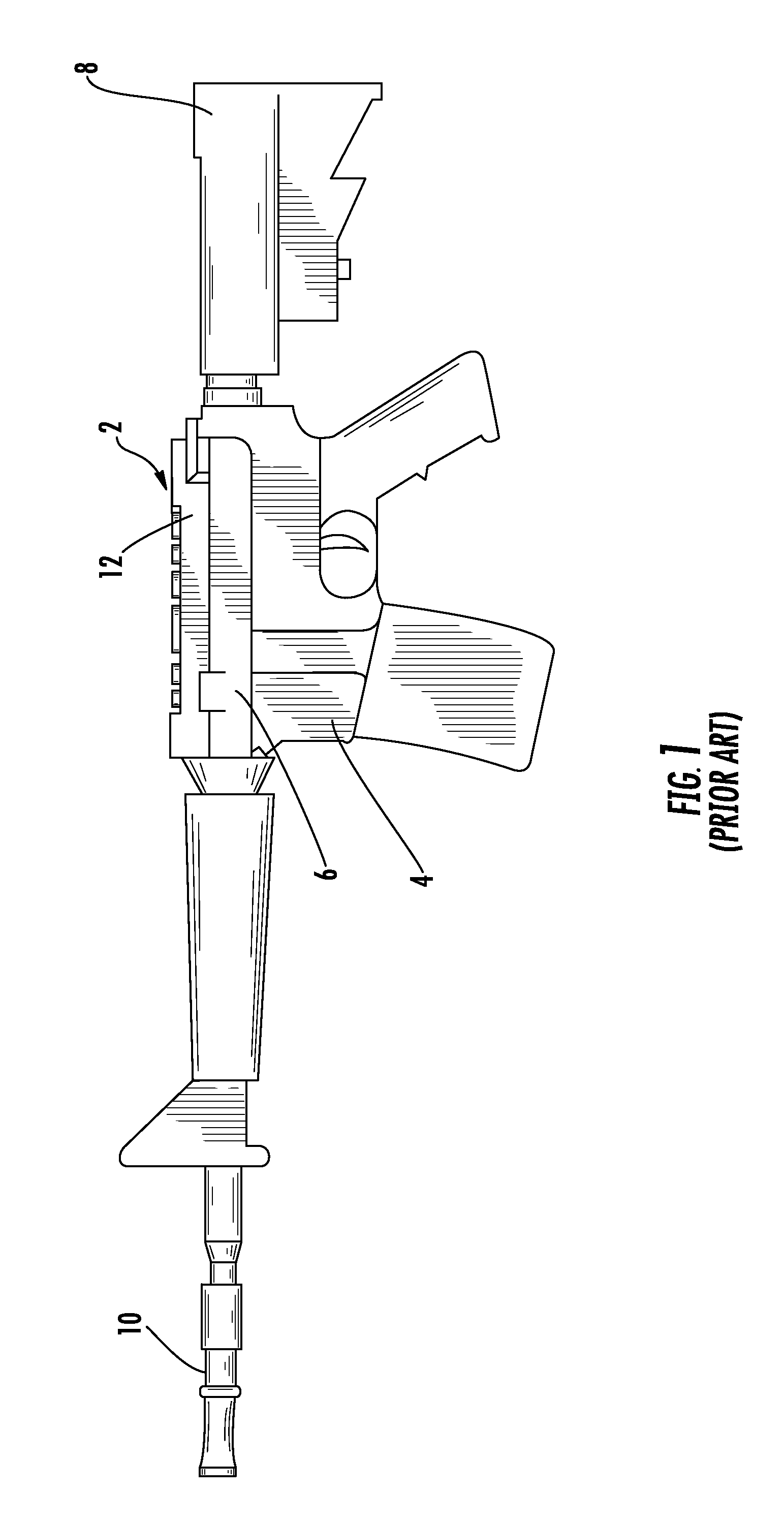
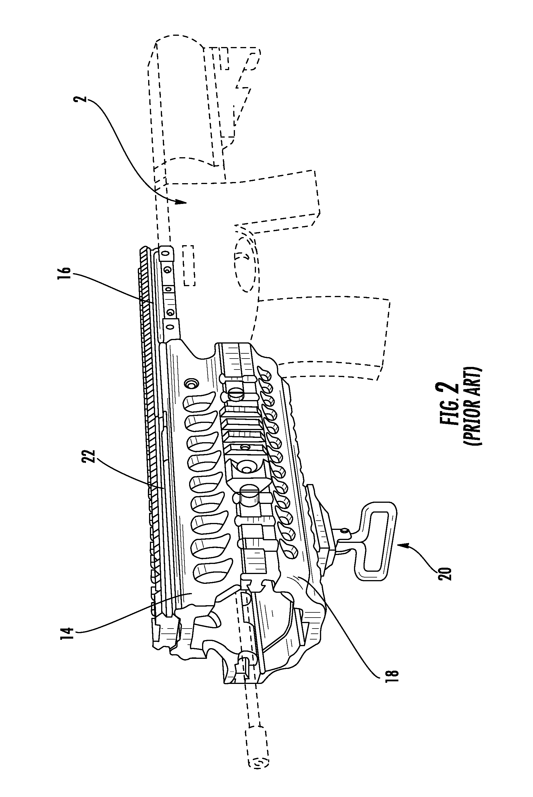
[0060]Turning now to FIGS. 7, 8 and 9, the mounting assembly 140 can be seen to include a main body 142 that is configured in substantially the same manner as a traditional prior art device and further includes a lower portion 143 that is configured to engage the dovetail rail 12 found on most modern combat weapons 2 and an upper portion 144 that can take on a variety of configurations depending on the accessory that is to be mounted thereon. As can best be seen in FIG. 9, the lower portion 143 of the main body 142 has a first engagement member 146 extending downwardly along one side thereof for engaging one side of the dovetail rail 12. Opposite the first engagement member 146, a boss formation 148 is provided adjacent the side of the main body 142 wherein the boss formation 148 includes a large central opening 150 therein to receive a clamping assembly generally indicated at 152. An annular bushing 164 with a smaller central opening 165 is installed into the large central opening ...

first embodiment

[0063]There is also shown a steel buffer pad 172 having a flat horizontal base portion with an arm 174 extending upwardly at an oblique angle of 135 degrees relative to the base. The free end of each arm 174 is curved approximately 150 degrees. Two side-by-side openings 176, corresponding in separation to the separation between buffer pad arms 174, are formed in the main body 142. The arms 174 of the buffer pad 172 are slid through the openings 176. In all respects, the buffer pad 172 operates as described in the first embodiment above.

[0064]Turning to FIG. 10, a third embodiment of the mounting assembly can be seen, and is generally indicated at 140A. The third embodiment is similar to the previous embodiment 140, including the same general components, main body 142, clamping assembly 152, etc. The differences are found in the manner of locking the retention nut 162 relative to the cam foot 154. Retention nut 162 no longer includes the nylon bushing 166. Rather, the nylon bushing 1...

fourth embodiment

[0065]Turning to FIGS. 11, 12 and 13, the mounting assembly 240 can be seen to include a main body 242 that is configured in substantially the same manner as a traditional prior art device and again includes a lower portion 243 that is configured to engage the dovetail rail 12 found on most modern combat weapons 2 and an upper portion 244 that can take on a variety of configurations depending on the accessory that is to be mounted thereon. As can best be seen in FIG. 13, the lower portion 243 of the main body 242 has a first engagement member 246 extending downwardly along one side thereof for engaging one side of the dovetail rail 12. Opposite the first engagement member 246, a boss formation 248 is provided adjacent the side of the main body 242 wherein the boss formation 248 includes a large central opening 250 therein to receive a clamping assembly generally indicated at 252. An annular bushing 264 with a smaller central opening 265 is installed into the large central opening 25...


PUM


Abstract

An improved mounting assembly is provided that is configured to be releasably attached to a standard dovetail rail profile, wherein the initial clamping tension of the clamping actuator is adjustable. The mounting assembly generally includes a main body having a lower portion that is configured to engage a standard dovetail and an upper portion accessory receiving formation. The lower portion of the mounting assembly has a first engagement member extending downwardly along one side thereof for engaging one side of the dovetail rail and a clamping assembly to engage the opposing side of the dovetail rail. At least one spring and a retention nut are provided as part of the clamping assembly such that a retention nut, which is locked relative to the clamping assembly, controls the preset spring tension thereby controlling the clamping force applied by the clamping assembly.

Description

CROSS-REFERENCE TO RELATED APPLICATIONS[0001]This application is a continuation-in-part of U.S. patent application Ser. No. 12 / 271,309, Filed Nov. 14, 2008, which is a continuation-in-part of U.S. patent application Ser. No. 11 / 933,506, Filed Nov. 1, 2007, which is related to and claims priority from earlier filed U.S. Provisional Patent Application No. 60 / 864,022, filed Nov. 2, 2006. The entire contents of all earlier filed applications are incorporated herein by reference.BACKGROUND OF THE INVENTION[0002]The present invention relates generally to modular integrated accessory mounting assemblies for combat weapons. More specifically, the present invention relates to an accessory mounting assembly, which includes an actuator that is incorporated into the accessory mount in a manner that provides adjustable spring tension to control the clamping force exerted by the actuator against the firearm interface rail.[0003]As the field of combat and commercial weaponry expands, numerous add-...

Claims


Application Information

Patent Timeline
IPC IPC(8): F41A35/04
CPCF41C23/16F41G11/003Y10T403/7071
Inventor SWAN, RICHARD E.
Owner SWAN RICHARD E
Why Eureka
Try Eureka