Two-stage hydrodynamic pump and method

a hydrodynamic pump and two-stage technology, applied in the direction of piston pumps, positive displacement liquid engines, liquid fuel engines, etc., can solve the problems of reducing the useful life of bearings and/or pumps, and achieve the effect of prolonging the li

Active Publication Date: 2010-07-20
TARK
View PDF81 Cites 16 Cited by
  • Summary
  • Abstract
  • Description
  • Claims
  • Application Information

AI Technical Summary

Benefits of technology

[0017]In yet another aspect, another embodiment provides a method for removing heat in a pump having a first stage area and a second stage area that is downstream of the first stage area, creating a pressure differential between the first stage area and the second stage area, providing an internal flow path from the second stage area to the first stage area such that at least a portion of the fluid being pumped by the pump is used to lubricate at least one bearing in the pump and to also cool the pump.

Problems solved by technology

One downside of the two-stage pumps of the past is that the bearings and the metal-to-metal contact of any rotating bearing members reduced the useful life of the bearings and / or the pump.

Method used


Image

  • Two-stage hydrodynamic pump and method
  • Two-stage hydrodynamic pump and method
  • Two-stage hydrodynamic pump and method

Examples


Embodiment Construction

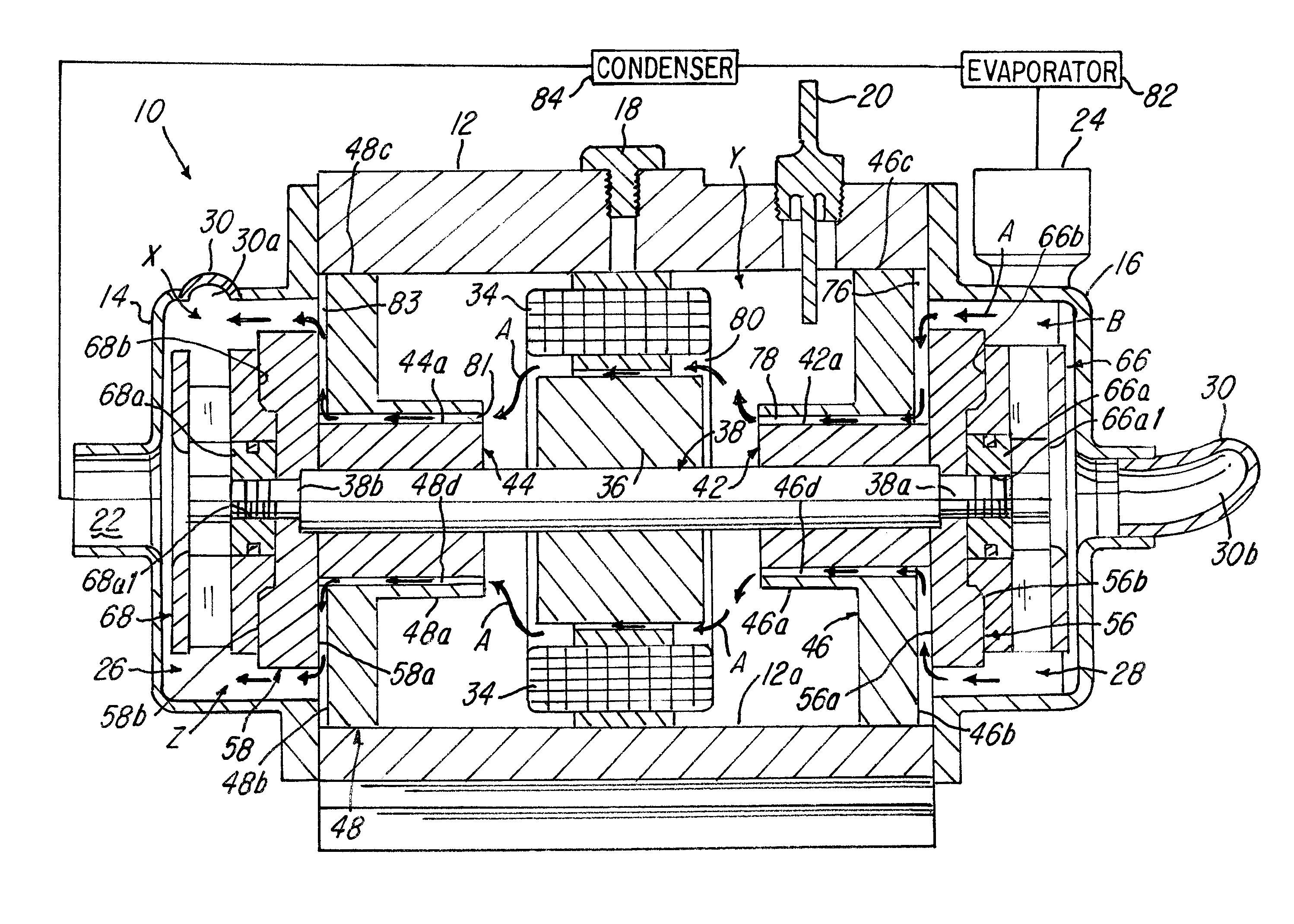
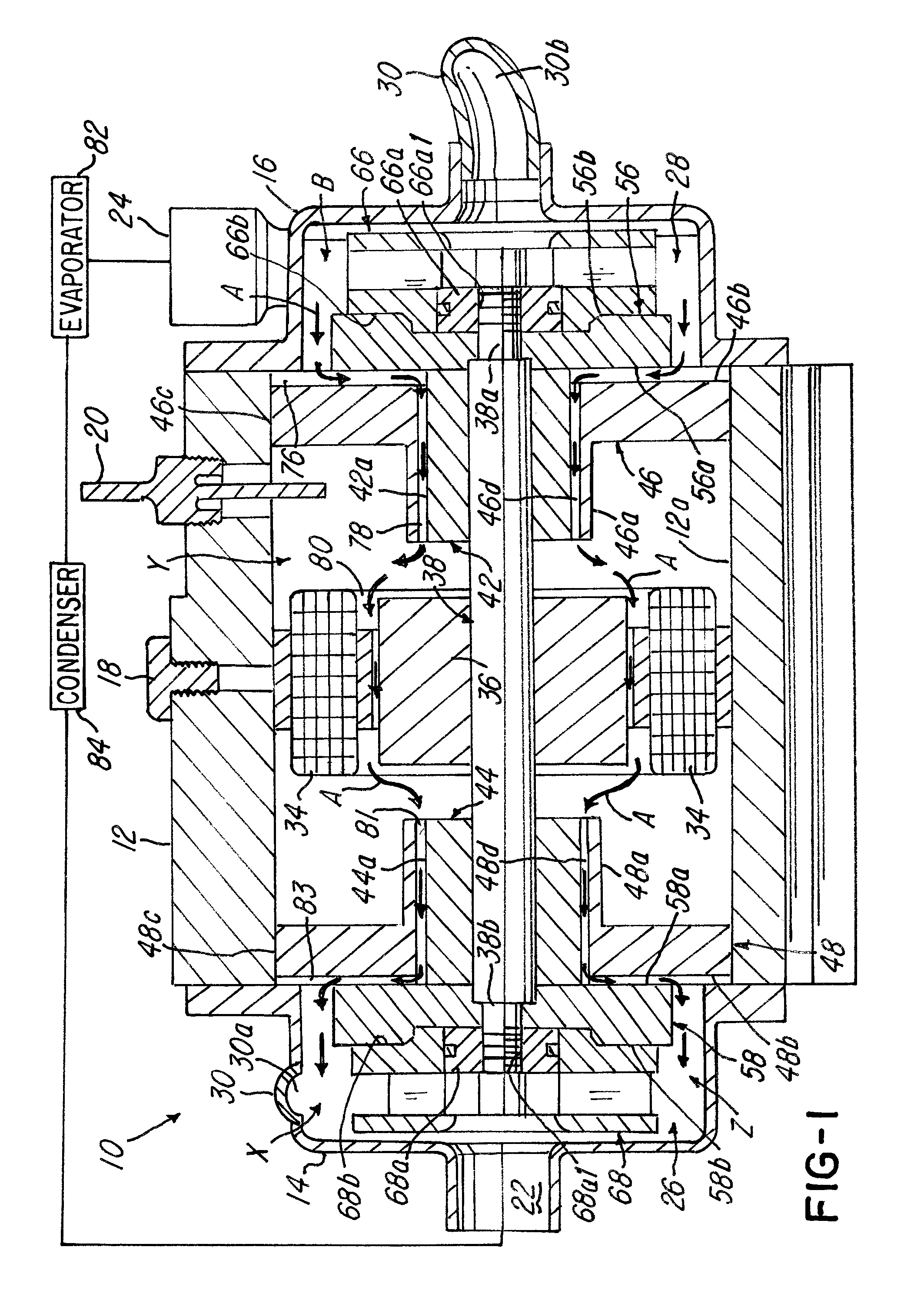
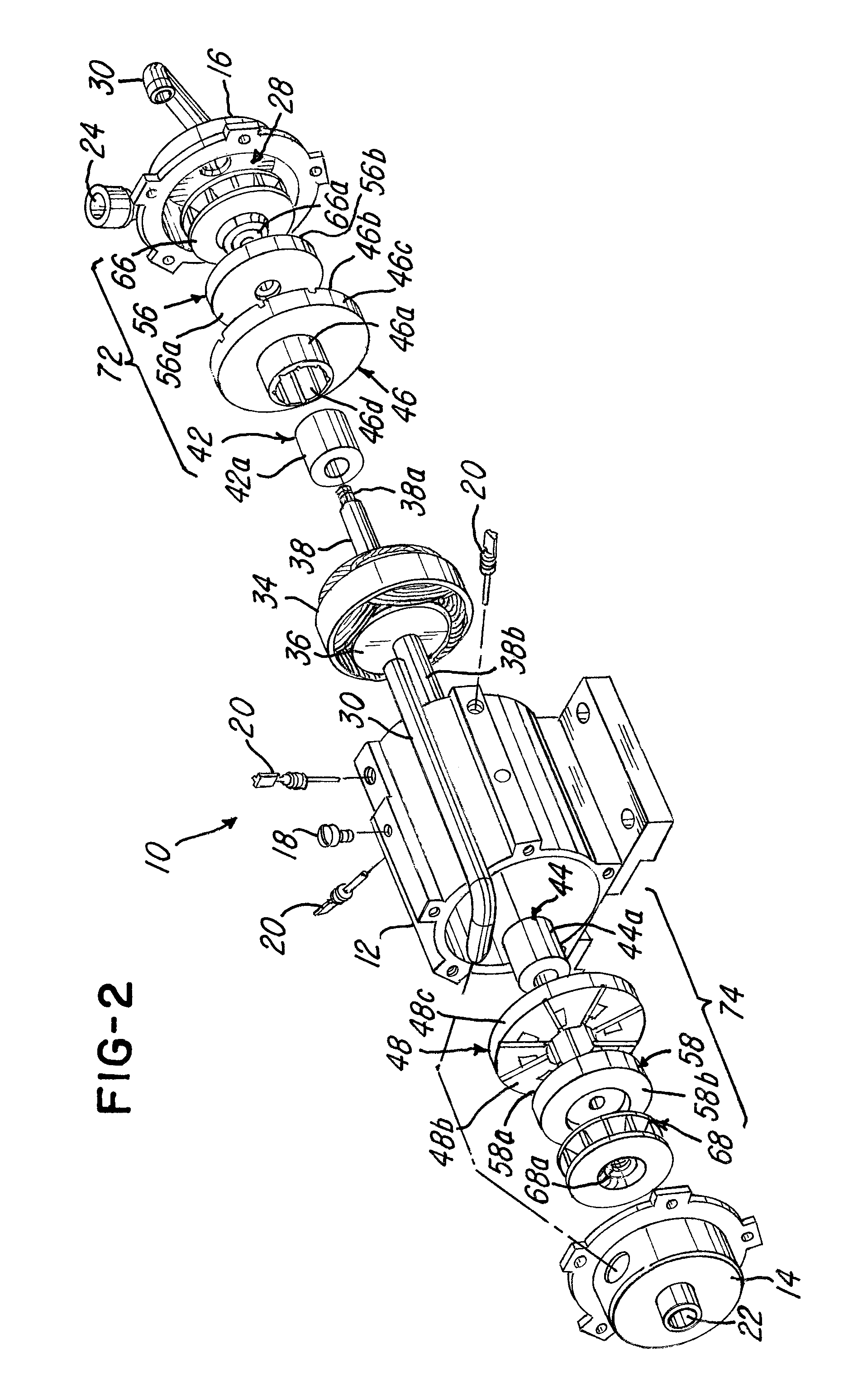
[0042]Referring now to FIGS. 1, 2 and 4, a pump in accordance with one embodiment of the invention is shown. In this embodiment, the pump 10 comprises a housing, a first end cap 14 and a second end cap 16. The pump 10 comprises a stator 34 and rotor 36 mounted on a shaft 38. The rotor 36 and stator 34 cooperate to provide an electric motor. A motor locking screw nut18 is provided in a housing wall 12a for locking the electric motor inside the housing 12 in a manner conventionally known. The housing 12 further comprises at least one or a plurality of hermetic connectors 20 in wall 12a which are also conventionally known.

[0043]The pump 10 comprises an inlet 22 and an outlet 24. The inlet 22 is in fluid communication with a first stage area 26, and the outlet 24 is in fluid communication with a second stage area 28. The first and second stage areas 26 and 28 are fluidly connected by a tubular member 30 (FIG. 2).

[0044]The pump 10 (FIG. 1) further comprises a first stationary journal bea...


PUM


Abstract

A two-stage pump having an internal fluid pathway or cycle for providing cooling to various parts in the pump, such as, an electric motor in the pump, and also for lubricating at least one or a plurality of bearings in the pump. The pump utilized hydrodynamic bearings that are adapted or configured to provide various passageways, channels and the like for using the fluid that is being pumped by the pump as lubrication for at least one or a plurality of bearings in the pump.

Description

BACKGROUND OF THE INVENTION[0001]1. Field of the Invention[0002]This invention relates to a two-stage hydrodynamic pump and, more particularly, to a pump that uses hydrodynamic bearings that are lubricated by fluid that is pumped by the pump and that cools.[0003]2. Description of the Related Art[0004]Two-stage pumps have been utilized in the past. One such pump is shown and described in U.S. Pat. No. 7,048,520. Typically, such pumps utilize bearings for any rotating parts in the pump. Typically, the bearings were metal-to-metal bearings that required lubrication.[0005]One downside of the two-stage pumps of the past is that the bearings and the metal-to-metal contact of any rotating bearing members reduced the useful life of the bearings and / or the pump.[0006]What is needed, therefore, is a system and method for improving the pump and extending the useful life of the pump.SUMMARY OF THE INVENTION[0007]One object of the invention is to overcome the problems of prior art pumps and to p...

Claims


Application Information

Patent Timeline
Patent Type & Authority Patents(United States)
IPC IPC(8): F04B39/02F16C31/06
CPCF04D17/122F04D25/0606F04D29/061F04D29/063F04D29/584F04D1/06F04D13/0653F04D29/588
Inventor PHAM, HOA DAOMCCARTHY, JOSEPH HOWARDCLEMENTZ, JAY TIMOTHYSTAHL, PHILIP
Owner TARK
Why Eureka
Try Eureka