
Object information acquisition apparatus and object information acquisition method

a technology of object information and acquisition apparatus, applied in the direction of instruments, diagnostic recording/measuring, and using reradiation, can solve the problems of long integration time, inability of the detector to efficiently inspect the human body, and inability to provide satisfactory sn ratio, etc., to achieve rapid and relatively easy acquisition of information, appropriate converge a thz beam, satisfactory sn ratio

Inactive Publication Date: 2010-07-27
CANON KK
View PDF45 Cites 11 Cited by
  • Summary
  • Abstract
  • Description
  • Claims
  • Application Information

AI Technical Summary

Benefits of technology

[0018]Thus, according to the present invention, tomographic information of an object such as a tomographic image is acquired by combining scanning only a necessary region with a THz-wave beam relatively having penetrating power and changing the intensity of the THz wave stepwise. Additionally, according to the present invention, tomographic information of an object such as a tomographic image is acquired by combining scanning only a necessary region with a THz-wave beam relatively having penetrating power and detecting the difference of arrival time, the intensity and so on of an electromagnetic wave by a detection unit. Therefore, it is possible to appropriately converge a THz beam and quickly and relatively easily acquire information on an object typically in the form of transmission images or reflection images at different levels in the direction of depth of the inside of the object with a satisfactory SN ratio and to detect an object that is not visible from the surface of another object hiding the object.

Problems solved by technology

However, a detector employing a THz wave as described above requires a large THz wave output power in order to irradiate a human body and does not provide a satisfactory SN ratio with the combination of a light source of a THz wave and a sensor as described above for the background art.
Additionally, such a detector requires a long integration time and hence it is not easy for the detector to inspect a human body efficiently within a short period of time.
Additionally, the above patent document does not describe anything about detecting the distribution of images along the height of an object in the inside thereof so that it may obviously be difficult to detect an article hidden in a thick object such as clothing or a shoe.
Particularly, no means is currently available to irradiate a shoe sole, and so it is not possible to detect an article hidden in a shoe.
Conventionally, a suspected shoe is required to be taken off and examined by means of X-rays, but this is a cumbersome operation and it is not possible satisfactorily to detect prohibited drugs and dangerous articles made of resin, particularly when they are not detectable by means of X-rays.

Method used


Image

  • Object information acquisition apparatus and object information acquisition method
  • Object information acquisition apparatus and object information acquisition method
  • Object information acquisition apparatus and object information acquisition method

Examples


example 1

[0050]FIG. 5 is a schematic illustration of the image acquisition apparatus of Example 1 according to the present invention, which is a shoe sole sensor, illustrating the specific configuration thereof. In FIG. 5, 50 denotes a relatively high (not less than the order of nW) output coherent continuous THz-wave generator, which is an AlGaAs / GaAs type quantum cascade laser in this example, although the present invention is by no means limited thereto. For example, a parametric oscillator using nonlinear optical crystal or a backward traveling wave oscillator may alternatively be used. The generator can generate a THz-wave with an output level of 30 mW and an oscillation frequency of about 3 THz as it is cooled to the temperature of liquid nitrogen. The generated THz-wave is collimated to a parallel beam of light with a beam diameter of about 12 mm by means of paraboloidal mirrors 51, 52 and converged to irradiate the sole of shoe 59, which is the object of examination, by means of lens...

example 2

[0054]FIG. 6 is a schematic illustration of the image acquisition apparatus of Example 2 according to the present invention. In this example, the existence or non-existence of a shoe sole on a supporting surface and, if exists, the area of existence are detected not by way of pressure but by way of light. In other words, the detection unit that detects an object of which property information is to be acquired of this example includes a unit that irradiates the area where the object is placed with light and acquiring a reflection image. Note that the components that are functionally same as those of Example 1 illustrated in FIG. 5 are not denoted by any reference symbols in FIG. 6 and will not be described here any further.

[0055]In this example, the detection unit that detects a shoe sole by means of light is coaxial with the THz optical system. Light generated from light source 62, which may typically be a halogen lamp, is transmitted through an ITO (indium tin oxide) mirror 63 and ...

example 3

[0059]FIG. 7 is a schematic illustration of the image acquisition apparatus of Example 3 according to the present invention. Unlike the preceding examples, not a coherent THz-wave source but a broad band light source using a THz-wave pulse is used in this example.

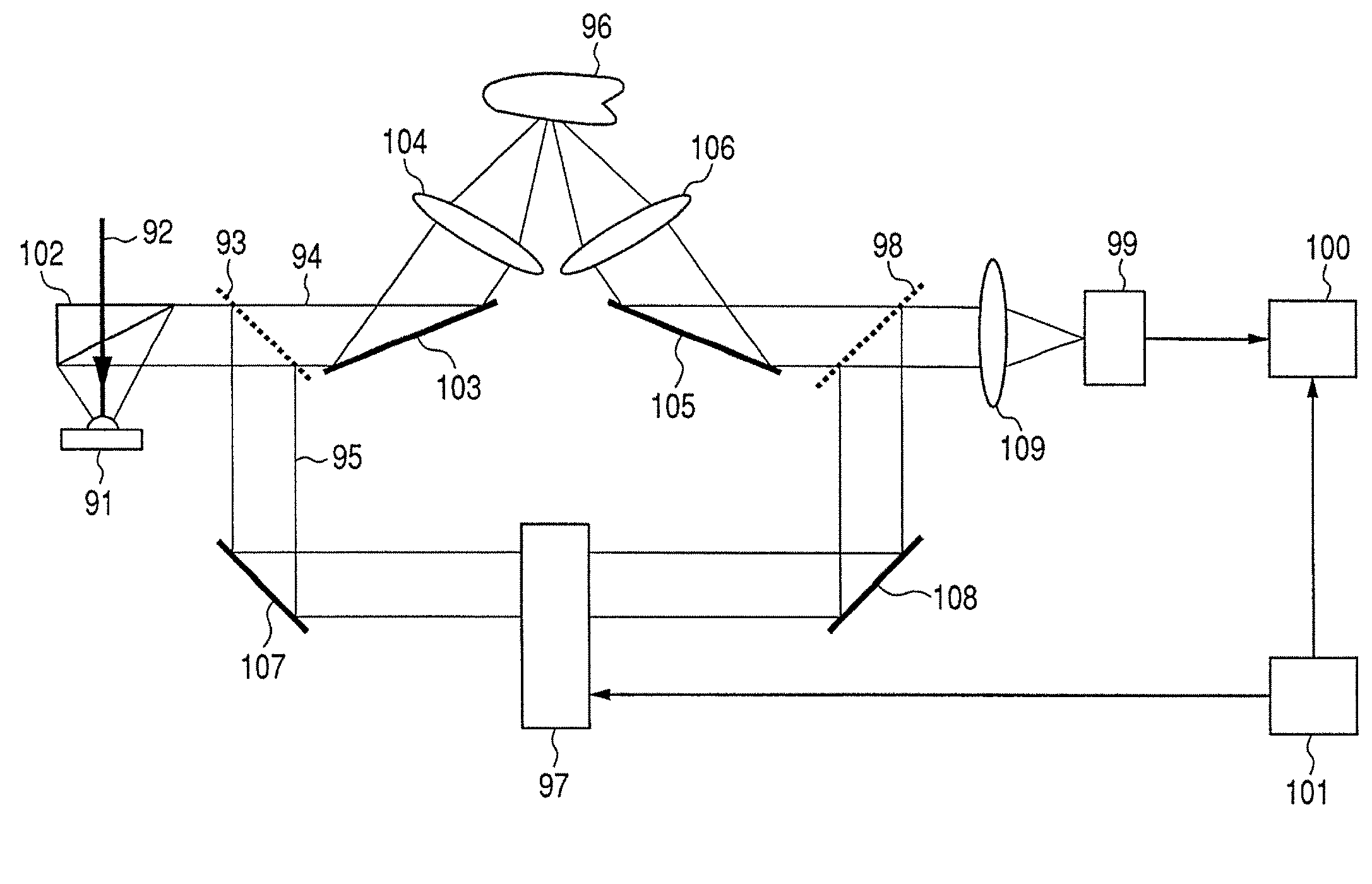
[0060]The apparatus of this example can be formed by using a terahertz time domain spectroscopy (THz-TDS). With the arrangement of FIG. 7, light from laser 70 adapted to generate a ultra-short pulse of 100 femtoseconds with a wavelength of 800 nm is irradiated onto photoconductive element 72 having a dipole antenna formed on the surface of crystal such as GaAs by way of a half mirror 85 and a chopper 71 that is driven by an oscillator 81. The photoconductive element 72 generates a terahertz wave as a voltage of 10 V is applied to the gap of the antenna. The terahertz wave is irradiated onto an object supporting surface 75 through a paraboloid mirror and a mirror 74 and scattered by the shoe sole (not illustrated) placed the...


PUM

PropertyMeasurementUnit
frequencyaaaaaaaaaa
output poweraaaaaaaaaa

Abstract

An object information acquisition apparatus for acquiring information on the inside of an object includes an electromagnetic wave generation unit capable of outputting a terahertz wave and of changing the output intensity, an irradiation unit that irradiates an electromagnetic wave onto an object, a scanning unit and a detection unit that detects the electromagnetic wave irradiated onto the object. The scanning unit changes the relative positions of the irradiated electromagnetic wave and the object. The detection unit detects the electromagnetic wave transmitted through or reflected by the object as a result of interaction of the object and the electromagnetic wave.

Description

BACKGROUND OF THE INVENTION[0001]1. Field of the Invention[0002]This invention relates to an object information acquisition apparatus such as an image acquisition apparatus and also to an object information acquisition method for acquiring information on an object by means of an electromagnetic wave. More particularly, the present invention relates to an image acquiring apparatus and an image acquisition method for observing the properties and the profile of an object by means of a high frequency electromagnetic wave in the domain of millimeter waves and terahertz waves (30 GHz to 30 THz).[0003]2. Description of the Related Art[0004]Non-destructive sensing technologies using electromagnetic waves within a range from millimeter waves to terahertz (THz)-waves (in a frequency range between 30 GHz to 30 THz, to be also referred to simply as “terahertz (THz) waves” hereafter) have been developed in recent years. Applicable fields of electromagnetic waves of the above-cited frequency band...

Claims


Application Information

Patent Timeline
Patent Type & Authority Patents(United States)
IPC IPC(8): G01S13/04G01N21/35G01B11/24G01N21/3563G01N21/3586
CPCG01N21/3581G01S7/28G01S13/887G01N21/3563A61B5/1074G01S13/89
Inventor OUCHI, TOSHIHIKOKAJIKI, KOUSUKEITSUJI, TAKEAKI
Owner CANON KK
Learn More