
Gas-phase functionalization of carbon nanotubes
a carbon nanotube and gas-phase technology, applied in the field of carbon nanotubes, can solve the problems of incompatibility of coating material or coating process, inability to guarantee reproducibility or uniformity of mwnt ald coating, and inability to achieve continuous ald coating onto a swnt by ald in general conventionally, so as to preserve the remarkable electrical, mechanical and optical properties
- Summary
- Abstract
- Description
- Claims
- Application Information
AI Technical Summary
Benefits of technology
Problems solved by technology
Method used
Image

Examples
example i
NO2 Adsorption and Desorption from a Carbon Nanotube
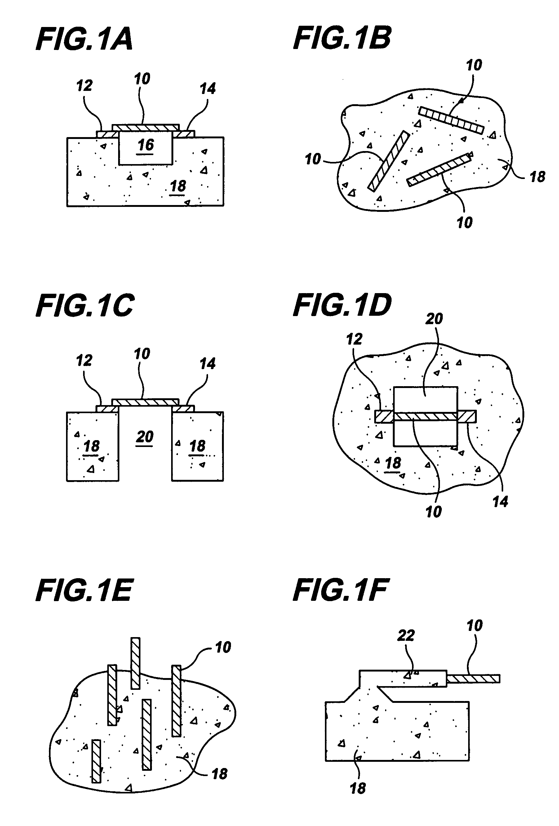
[0075]The electrical conductance of SWNTs was experimentally analyzed during the functionalization procedure of the invention. To produce structures for analysis, optical lithography and electron beam evaporation techniques were employed to pattern metal electrodes of 50 nm-thick Mo and 50 nm-thick Ti layers on quartz substrates. A focused ion beam (FIB) was employed to form trenches of 1 μm in width and 0.5 μm in depth between the edges of the metal electrodes. A layer of approximately 0.5 nm in thickness of Al2O3 was deposited by ALD on the electrode surfaces to prevent alloying between the molybdenum and the nanotube catalyst metal subsequently deposited. A catalyst region of Co of about 0.3 nm in thickness was deposited and patterned by liftoff on the electrode surfaces to form isolated catalyst regions.
[0076]SWNT synthesis was carried out at atmospheric pressure by bubbling argon at a flow rate of about 450 sccm through ethano...
example ii
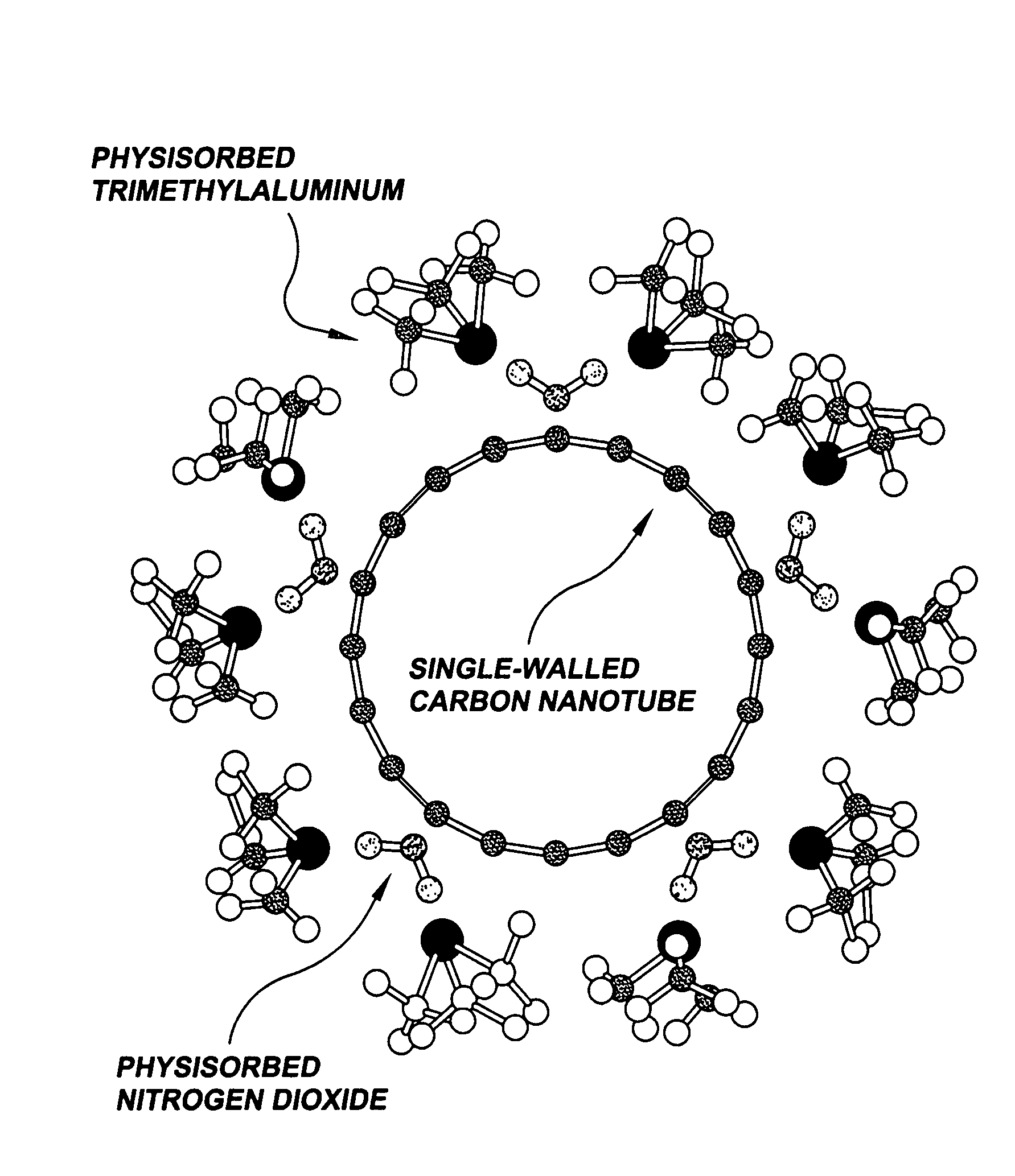
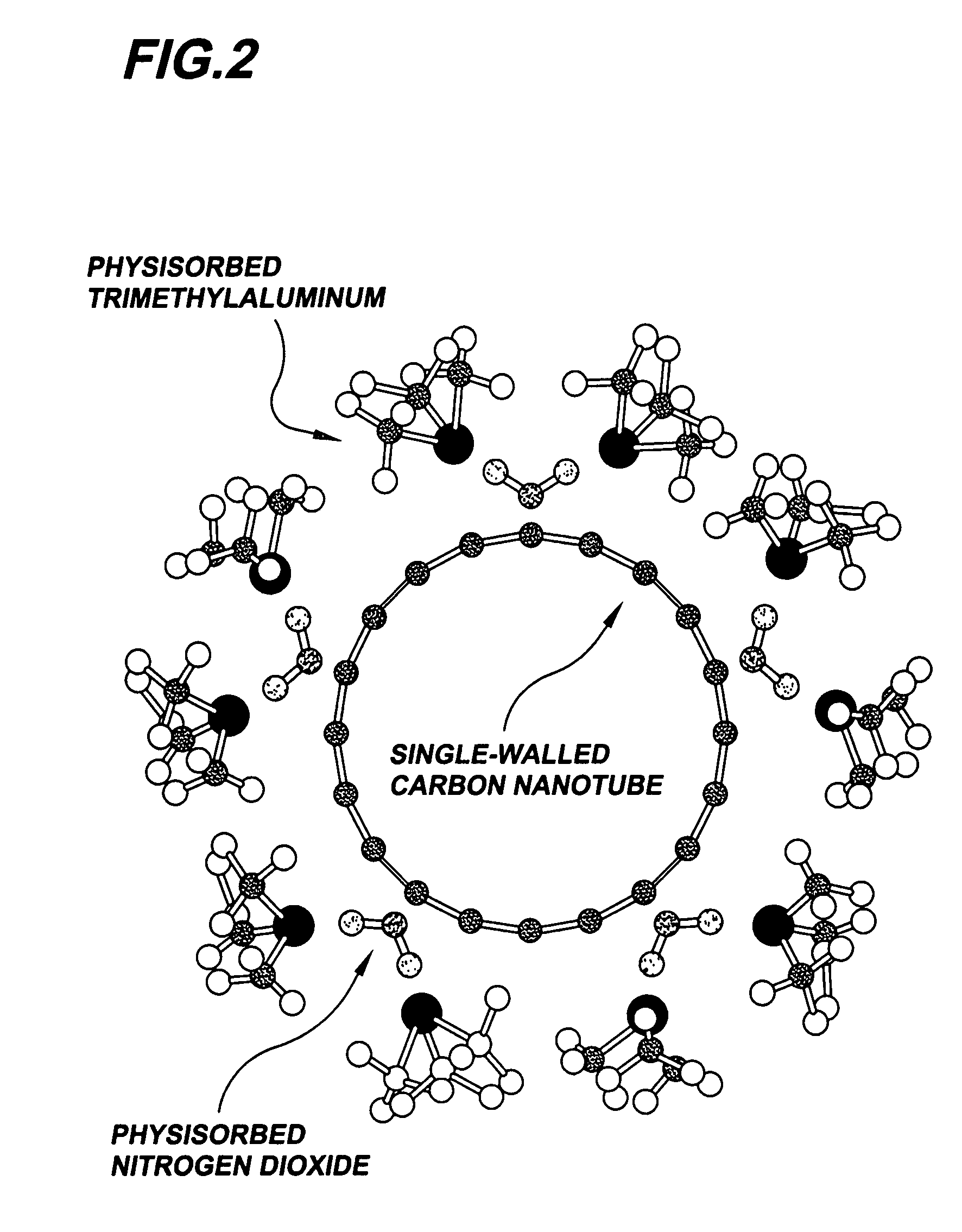
TMA Stabilization of Adsorbed NO2
[0080]Suspended SWNTs were fabricated in the configuration of Example I and exposed to pulsed dosing of TMA. Here approximately 6 mL doses of TMA at a pressure of about 10 Torr were pulsed over suspended SWNTs under the same conditions that were used in the NO2 pulsing of Example I. During the pulsed dosing the conductance of the SWNTs was measured.
[0081]FIG. 3B is a plot of measured conductance of a SWNT as a function of time during pulsed TMA dosing. TMA exposure has an effect on the conductive properties of SWNTs that is the opposite of that due to NO2 exposure, and thus causes a decrease in SWNT conductance. The measured SWNT conductance following a TMA pulse exposure is seen in the plot to recover slightly due to desorption after each pulse, but it does not return to a constant baseline value as it did with NO2 exposure. This results in an overall negative slope in the conductance / time profile, which may be due to an increase in contact resista...
example iii
Functionalization Layer Thickness Control by ALD Cycle Number
[0084]SWNTs were synthesized as in Example I. The SWNTs were subjected to various NO2-TMA functionalization processes, with the number of NO2-TMA functionalization cycles adjusted to elucidate the nature of the resulting functionalization layer. For each process, a vacuum pressure of about 300 mTorr, under the continuous flow of argon at a flow rate of about 50 sccm, at a temperature of about 25° C., was employed. One functionalization cycle consisted of a 30 mL NO2 vapor dose at about 960 Torr followed by a 2 min purge with argon, then a 6 mL TMA vapor dose at about 10 Torr, followed by a 2 min purge. FIG. 4A is a plot of the thickness of the functionalization layer as a function of the number of NO2-TMA cycles.
[0085]As shown in the plot, the thickness of the functionalization layer remained constant at about one monolayer for up to about 100 NO2-TMA cycles. This preserved functionalization layer thickness within the firs...
PUM
| Property | Measurement | Unit |
|---|---|---|
| thickness | aaaaa | aaaaa |
| temperatures | aaaaa | aaaaa |
| thickness | aaaaa | aaaaa |
Abstract
Description
Claims
Application Information