Multi-function tool

a multi-functional, tool technology, applied in the direction of multi-purpose tools, wrenches, crowbars, etc., can solve the problems of inability to fully pull out the nail, the distance between the pry bar and the handle cannot be adjusted, and it is difficult to find a supporting fulcrum

Active Publication Date: 2010-08-17
LIOU MOU TANG
View PDF12 Cites 24 Cited by
  • Summary
  • Abstract
  • Description
  • Claims
  • Application Information

AI Technical Summary

Problems solved by technology

However, the tool is usually formed as one piece, and the distance between the pry bar and the handle cannot be adjusted.
Thus, the tool is just adapted for pulling nails whose size is limited to a particular range, and if the nail is of a size over the range, the tool could not pull out the nail fully.
Moreover, when a user operates the tool to pry something on a narrow place, it is difficult to find a fulcrum for supporting.

Method used


Image

  • Multi-function tool
  • Multi-function tool
  • Multi-function tool

Examples


first embodiment

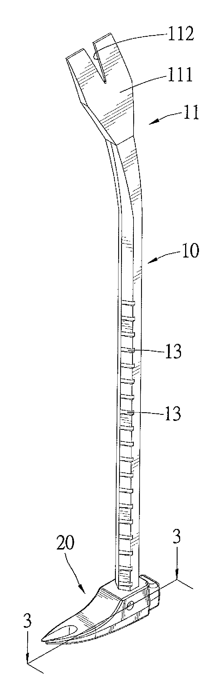
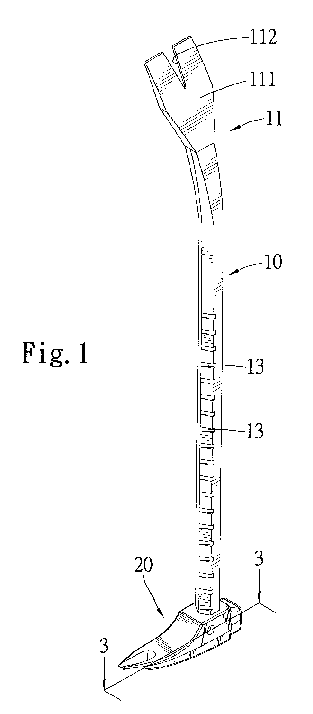
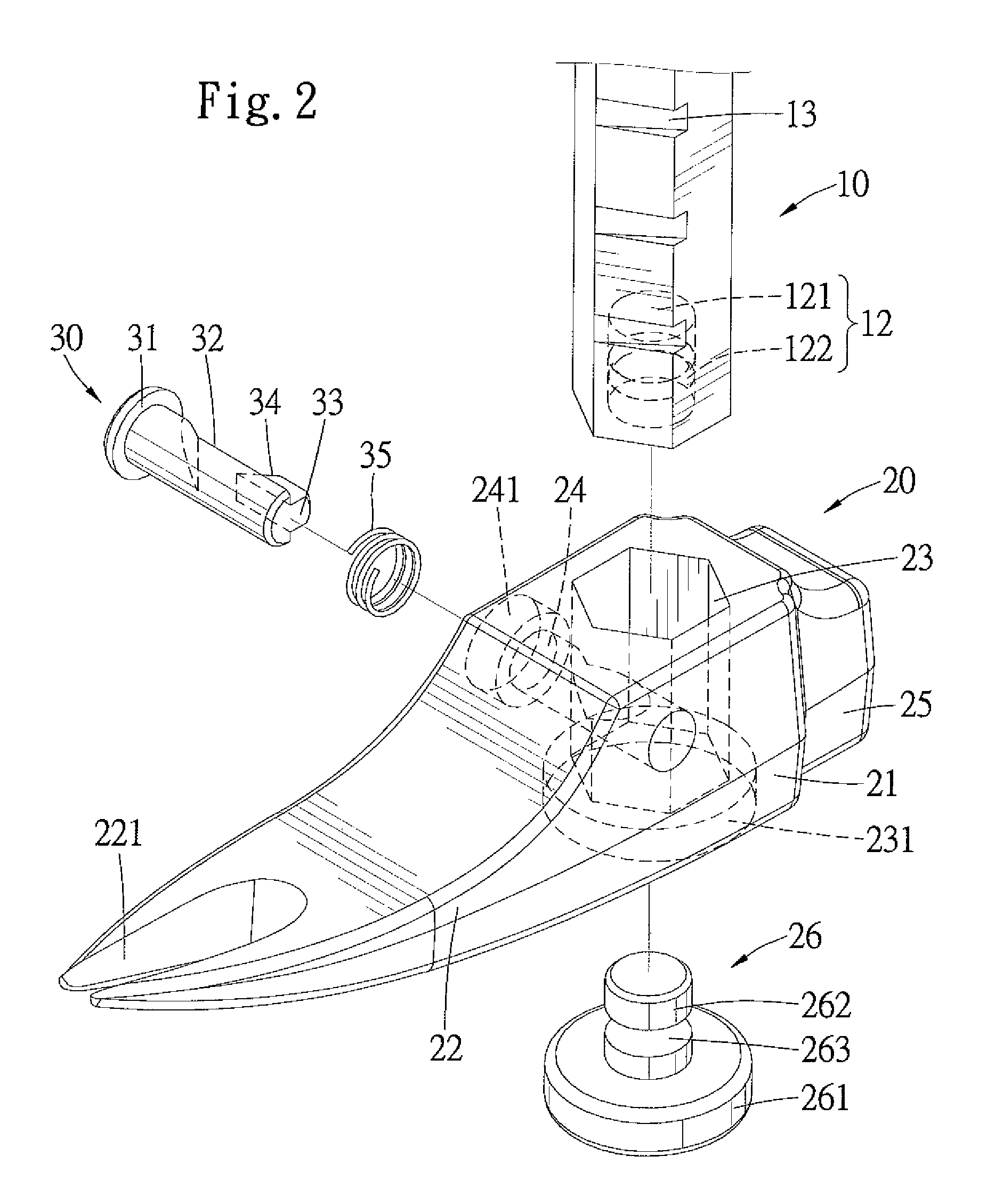
[0022]Referring to FIGS. 1 through 3, a multi-function tool in accordance with a first embodiment in the present invention, includes a hexagonal shank body 10, a pry bar 20 slidably mounted on the shank body 10 longitudinally and a clutch 30 coupling the pry bar 20 to the shank body 10.

[0023]The shank body 10 includes a first end 11 and a second end 12. A head portion 111 is formed on the first end 11 and is capable of prying materials on narrow conditions. A slot 112 is defined on the center of the head portion 111 for nail pulling. The second end 12 includes a receiving portion 121 formed therein longitudinally and opening to outside thereof, and a projection 122 is annularly formed on the inner wall of the receiving portion 121. A plurality of positioning grooves 13 are defined on the outer periphery of the shank body 10, with the positioning grooves 13 aligned from the second end 12 to the first end 11. The, interval between each of the positioning grooves 13 is alternatively co...

fourth embodiment

[0029]FIG. 11 shows a fourth embodiment in the present invention. A multi-function tool includes a hexagonal shank body 10b, a handle 50 and a joint 60 connecting the shank body 10b and the handle 50 to each other. The shank body 10b is similar to the shank body 10, wherein like numerals are employed to denote like components of the prior embodiment, however bearing the suffix “b ”. A bent portion 14b is defined between the first and second ends 11b and 12b so that the head portion 111b is approximately L-shaped. A jaw surface 15b is defined on the bottom surface of the head portion 111b. The handle 50 is hollow and includes a first end defining a hole 51 therein for receiving the second end 12b of the shank body 10b and a second end for a user to hold. The joint 60 is disposed between the shank body 10b and the handle 50 and includes a through-hole 61 and a receptacle 62 piercing therethrough, respectively. The direction of axis of the through-hole 61 is parallel to that of the sec...


PUM


Abstract

A multi-function tool has a shank body including a first end, a second end and a plurality of positioning grooves formed between the first and second ends thereof. A pry bar includes a connected section and a working section extending from a side of the connected section for pulling nails. A through-hole pierces the connected section for slidably receiving the shank body, with a second receptacle piercing the connected section and in communication with the through-hole. A clutch is disposed in the second receptacle for alternatively engaging with a selected one of the positioning grooves.

Description

BACKGROUND OF THE INVENTION[0001]1. Field of the Invention[0002]The present invention relates to a multi-function tool adapted for nail pulling and prying. More particularly, the present invention relates to a multi-function tool having a pry bar whose location thereon is adjustable.[0003]2. Description of the Related Art[0004]A conventional tool for nail pulling and prying material on the surface includes a pry bar formed on an end thereof and a handle formed on another end thereof. However, the tool is usually formed as one piece, and the distance between the pry bar and the handle cannot be adjusted. Thus, the tool is just adapted for pulling nails whose size is limited to a particular range, and if the nail is of a size over the range, the tool could not pull out the nail fully. Moreover, when a user operates the tool to pry something on a narrow place, it is difficult to find a fulcrum for supporting.[0005]Therefore, the present invention is intended to obviate or at least alle...

Claims


Application Information

Patent Timeline
Patent Type & Authority Patents(United States)
IPC IPC(8): B66F15/00B25D1/04B25F1/00B25B13/10
CPCB25F1/00B25G1/04B66F15/00
Inventor LIOU, MOU-TANG
Owner LIOU MOU TANG
Why Eureka
Try Eureka