Combustion nozzle fluidic injection assembly

a technology of fluid injection and combustion nozzle, which is applied in the direction of machine/engine, intermittent jet plant, vessel construction, etc., can solve the problems of undesirable performance drawback, restricted geometry options, weight and maintenance requirements are significant requirements,

Inactive Publication Date: 2010-08-17
UNITED TECH CORP
View PDF18 Cites 28 Cited by
  • Summary
  • Abstract
  • Description
  • Claims
  • Application Information

AI Technical Summary

Problems solved by technology

However, mechanical complexity, restrictive geometry options, weight and maintenance demands are significant requirements for most variable geometry nozzle designs.
Many require excessive engine bleed flows, which presents an undesirable performance drawback.
Compressor bleed air is “expensive” air, and combustion nozzle fluidic injection system that utilize compressor bleed air present a particularly undesirable drain on engine efficiency by decreasing the mass of the primary gas turbine engine flow.
Moreover, existing designs are often relatively large and heavy.

Method used


Image

  • Combustion nozzle fluidic injection assembly
  • Combustion nozzle fluidic injection assembly
  • Combustion nozzle fluidic injection assembly

Examples


first embodiment

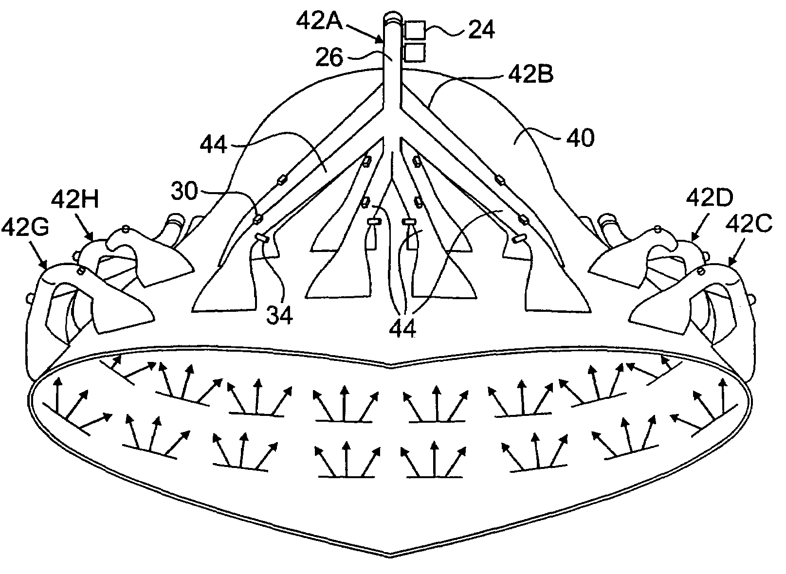
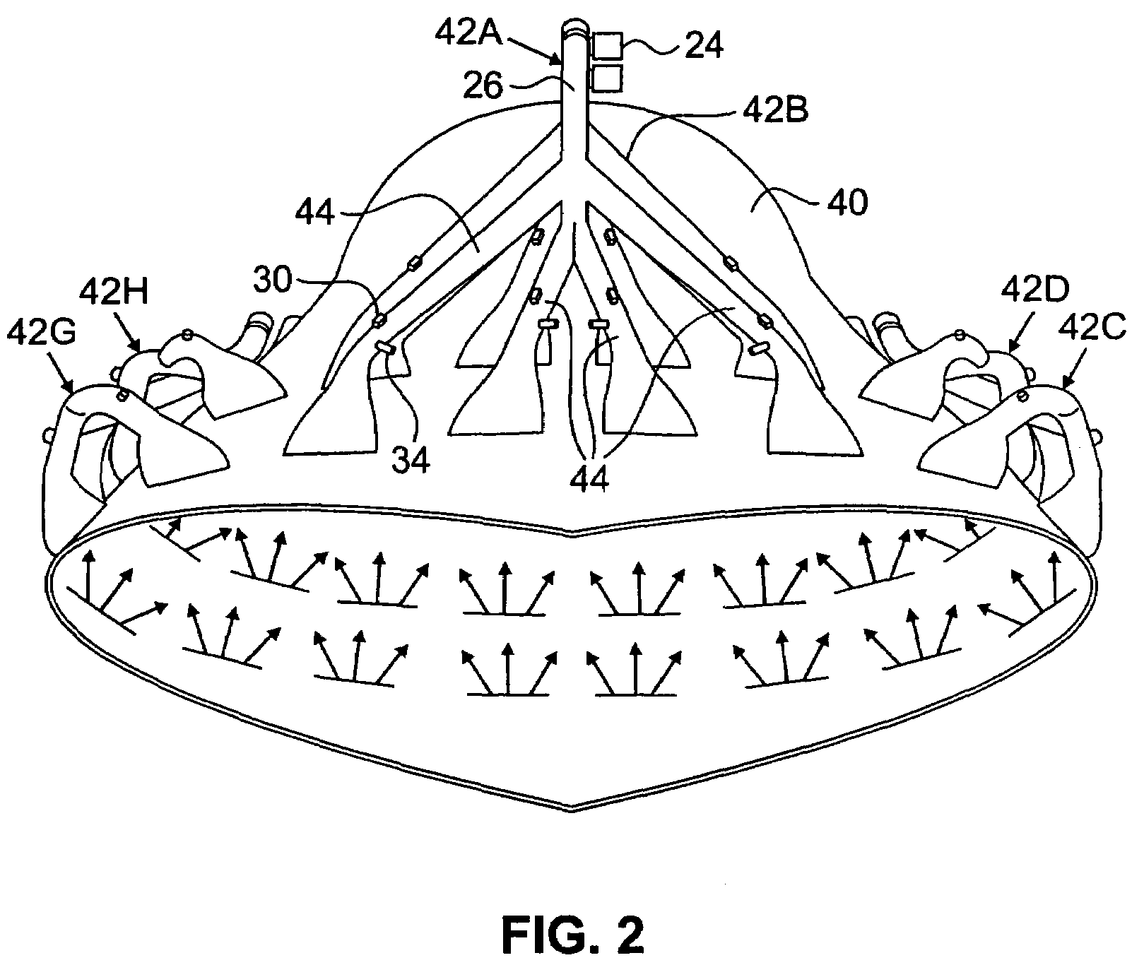
[0021]FIG. 2 is a perspective view of a combustion nozzle 40 utilizing a number of fluidic injection assemblies. The combustion nozzle 40 has a fixed geometry in a conventional converging-diverging shape. However, it should be recognized that in further embodiments the combustion nozzle 40 can have other suitable shapes beyond the illustrated shape, as desired. Mounted relative to the combustion nozzle are eight fluidic injection assemblies 42A-42H (assemblies 42E and 42F are not visible in FIG. 2). Each fluidic injection assembly 42A-42H can be similar to that described with respect to FIG. 1. As shown with respect to fluidic injection assembly 42A (reference numbers have been omitted from the other fluidic injection assemblies 42B-42H for simplicity), each assembly 42A-42H includes a bleed air valve 24, a distribution manifold 26, and four fluidic injection subassemblies 44.

[0022]Operation of the fluidic injection assemblies 42A-42H can be controlled to adjust effective nozzle are...

second embodiment

[0032]Alternative embodiments of fluidic injections assemblies according to the present invention are contemplated. FIG. 5 is a schematic cross-sectional view of a fluidic injection subassembly 150. The subassembly 150 includes a fluidic injector subassembly 50 similar to that described with respect to FIG. 3. The subassembly 50 is positioned within an inlet portion 152 of a secondary tube 154. The subassembly 50 defines a cross-sectional area A1, and the inlet portion of the secondary tube 154 defines a cross-sectional area A2. The inlet portion 152 of the secondary tube 154 provides a generally annular secondary flowpath for secondary bleed air (e.g., liner cooling air, fan bleed air or compressor bleed air) to flow past the subassembly 50. A mixing tube 156 is connected to the downstream end of the inlet portion 152 of the secondary tube 154. Secondary bleed air from the secondary tube 154 and primary exhaust flow from the subassembly 50 combine in the mixing tube 156. Primary ex...


PUM


Abstract

A fluid flow system for use with a gas turbine engine includes an exhaust nozzle, a primary air supply valve, a distribution manifold connected to the primary fluid supply valve and in fluid communication therewith, and a plurality of fluid injector assemblies positioned at the exhaust nozzle and connected in fluid communication with the distribution manifold. Each fluid injector assembly includes a first tube, a secondary air valve positioned at least partially within the first tube and in fluid communication with the distribution manifold, a fuel valve positioned at least partially within the first tube and located downstream of the air valve, an igniter extending into the first tube downstream of the fuel valve, and an outlet in fluid communication with the first tube and connected in fluid communication with the exhaust nozzle. The outlet has a different geometry than the first tube.

Description

BACKGROUND OF THE INVENTION[0001]The present invention relates to fluidic injection systems for use with combustion engines, and more particularly to fluidic injection assemblies for controlled injection of fluid relative to an exhaust nozzle of a gas turbine engine.[0002]In order to implement an augmented gas turbine engine cycle, a variable area nozzle is generally required to provide proper engine backpressure and flow matching throughout an operational range. Variable geometry nozzles for aircraft engines are well-known in the art as a means for providing nozzle throat area control and nozzle exit area control. These systems use mechanically actuated deflectors or other mechanical structures to control physical nozzle area characteristics. Some variable geometry nozzles can also provide thrust vectoring, that is, controllable deflection of exhaust gas flow. However, mechanical complexity, restrictive geometry options, weight and maintenance demands are significant requirements f...

Claims


Application Information

Patent Timeline
Patent Type & Authority Patents(United States)
IPC IPC(8): B63H25/46F02K1/00
CPCF02C6/08F02K1/002F02K1/28F02K1/38F02K7/02F02K9/82
Inventor BERG, GERALD R.MESSERSMITH, NATHAN L.LIDSTONE, GARY L.HINKEY, JOHN
Owner UNITED TECH CORP
Why Eureka
Try Eureka