Greenough-type stereomicroscope

a stereomicroscope and greenough technology, applied in the field of greenough stereomicroscopes, can solve the problems of limited stereoscopic viewing, high depth of focus, and difficulty in merging two partial images into a three-dimensional image, and achieve the effect of improving detail recognition and increasing the convergence angl

Active Publication Date: 2010-08-17
LEICA INSTR SINGAPORE PTE
View PDF34 Cites 33 Cited by
  • Summary
  • Abstract
  • Description
  • Claims
  • Application Information

AI Technical Summary

Benefits of technology

[0014]An object of the invention is to provide a Greenough-style stereomicroscope which has improved detail recognition compared to Greenough stereomicroscopes of conventional design without this leading to an increase in the convergence angle and hence the construction volume as well.
[0016]It is advantageous if at least one optical element in the first beam path of the first microscope has a different optically effective diameter compared to at least one corresponding optical element in the second beam path of the second microscope. The term “optically effective diameter” means the diameter which describes the pencil of rays contributing to the image generation when they hit an optical element which they penetrate.
[0017]It is now possible to provide stereomicroscopes according to the invention which on the one hand have great depth of focus as a result of a small numerical aperture at low magnifications and permit good 3-D representation and on the other hand have a high aperture at high magnifications and therefore provide high resolution without producing needless or empty magnifications (increase in magnification without increased recognition of details, i.e. with the same resolution). Furthermore, the detail recognition can be improved compared with stereomicroscopes of conventional construction without increasing the angle of convergence and hence the construction volume.
[0021]It is particularly advantageous if an optical axis of the first microscope and an optical axis of the second microscope are arranged symmetrically to a perpendicular in an object plane. This symmetrical arrangement has the advantages that the exit pupils are at the same height above the object and hence the user can look without bending his head to the side, thus avoiding an unergonomic position of the head. In this arrangement the channel with the greater depth of focus also improves the perceived depth of focus overall.
[0024]However, it may be advantageous to mount the unit comprising the two microscopes with a fixed convergence angle such that the angles between the optical axes of the microscopes and the perpendicular are adjustable. For example, the unit may be tilted such that the microscope with the greater optically effective diameter is at a smaller angle to the perpendicular than the other microscope. This adjustment is advantageous because of the reduced lack of definition at the edges, particularly when the microscope with the greater optically effective diameter is used for documentation purposes.
[0025]It is advantageous if at least one filter can be positioned in the beam path of the first microscope with the higher numerical aperture. This results in an adaptation of the brightness between the first and second beam paths. Here the filter may be designed as a filter that is homogeneous over the entire surface. Furthermore, the filter can also be designed as a graduated filter. In this case a change in brightness dependent on the magnification can be compensated by moving a filter. Moving or changing and generally positioning a filter may be carried out manually or by automation, particularly as a function of the magnification selected.

Problems solved by technology

Since the optical axes of the two microscopes meet the object at an oblique angle, a large convergence angle is detrimental to the in-focus reproduction of the edges of the object and makes merging of the two partial images into a three-dimensional image difficult.
Therefore in this case stereoscopic viewing, which is possible only in the area of overlap, is restricted.
At low magnifications, on the other hand, the overlap is great but the numerical aperture is small, resulting in a high depth of focus.
Such correction is not possible with direct visual observation such as occurs in stereomicroscopes.
The problem underlying the somatic microscope in this specification is based on the fact that when two objectives are used they cannot be arranged as close together as is desired, as the objective used is a lens combination and it is impossible to use a single objective lens because of the increasing spherical aberrations, particularly when work is to be done under high magnification.

Method used


Image

  • Greenough-type stereomicroscope
  • Greenough-type stereomicroscope
  • Greenough-type stereomicroscope

Examples


Embodiment Construction

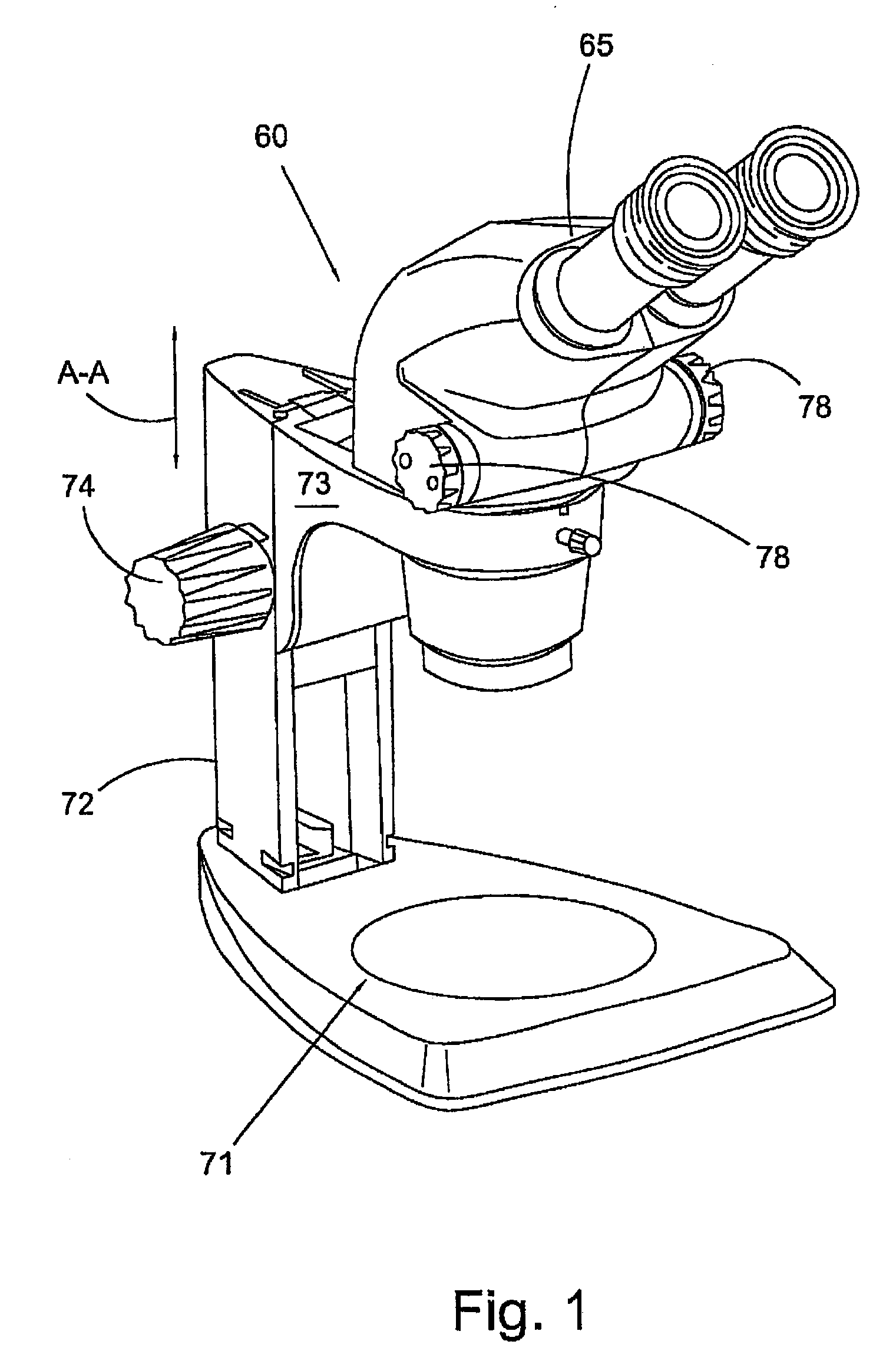
[0040]FIG. 1 is a perspective view of a Greenough-style stereomicroscope 60 according to the prior art. The stereomicroscope 60 comprises a base 71, to which a focusing column 72 is secured. A focusing arm 73 is movably mounted on the focusing column 72, and can be displaced by means of adjustment elements 74 along the double arrow A-A. The stereomicroscope 60 has a binocular tube 65 and a zoom system (see FIG. 2). The zoom system can be adjusted by adjusting elements 78. Instead of a continuously operating zoom system an objective changer which discretely changes the magnification may be provided.

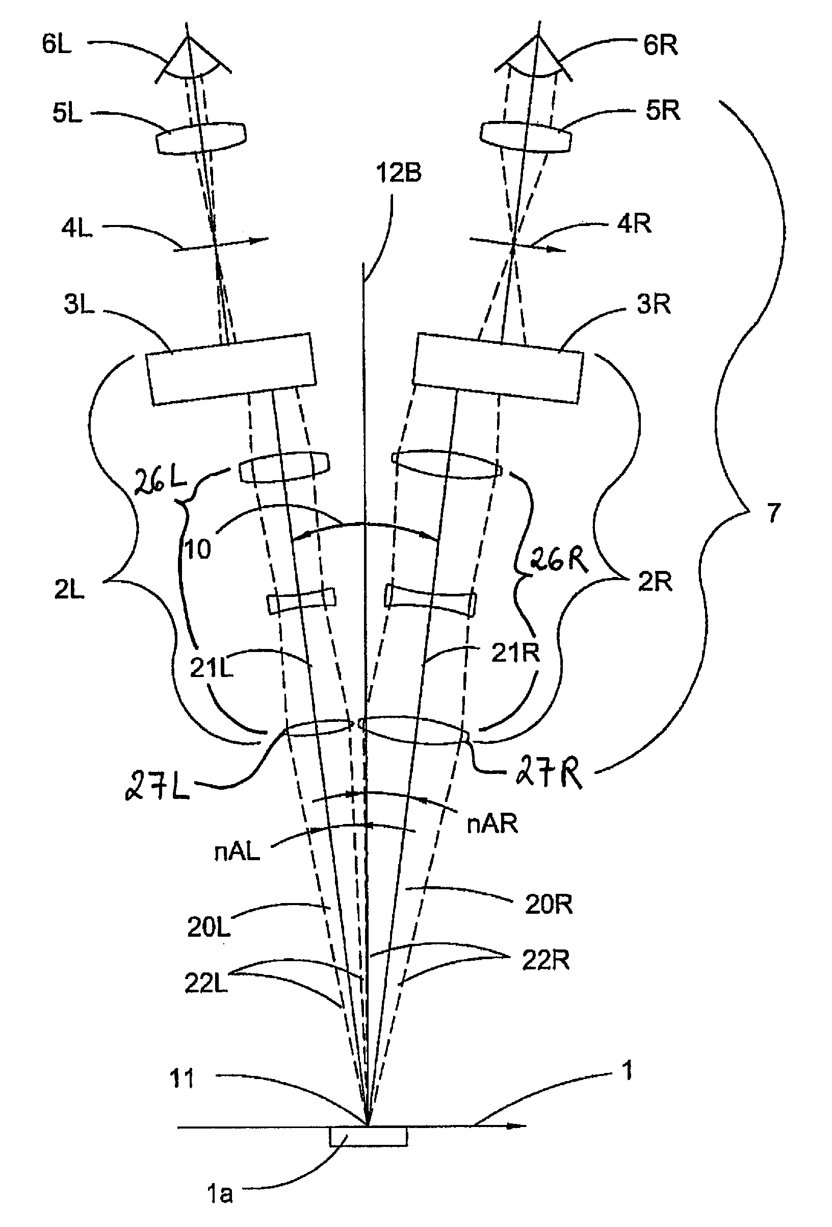
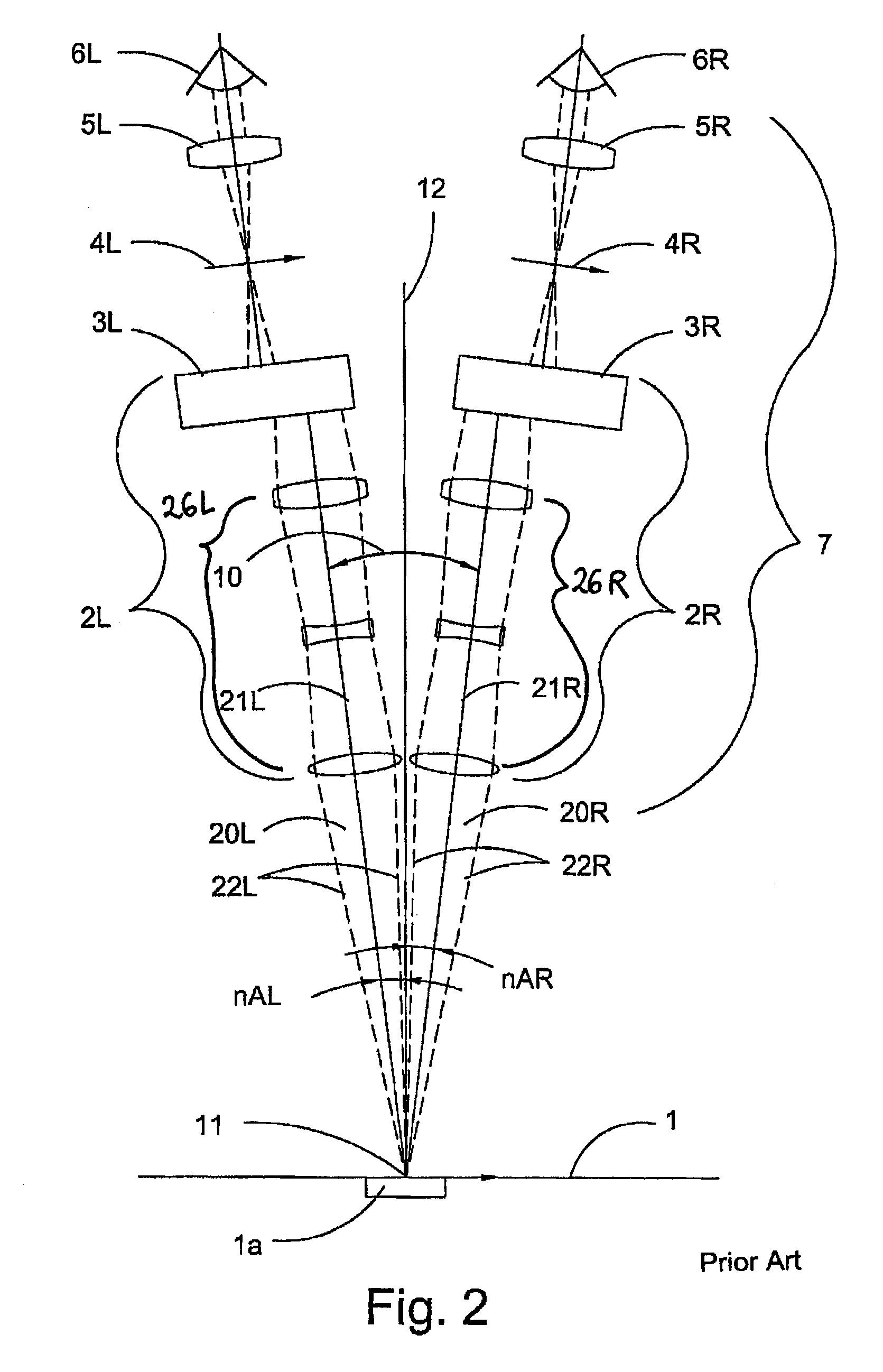
[0041]FIG. 2 is a schematic diagram of the optical design of a Greenough-style stereomicroscope 7 according to the prior art. The Greenough-style stereomicroscope 7 is constructed from a first monocular microscope 2R and a second monocular microscope 2L. The two microscopes 2R and 2L are constructed symmetrically in such a way that both microscopes 2R and 2L have the same focal point 11. T...


PUM


Abstract

A stereomicroscope of the Greenough type includes a first monocular microscope and a second monocular microscope, which define a first beam path and a second beam path, respectively, wherein the first and second microscopes are arranged at a convergence angle to one another and comprise magnification systems for producing equal magnifications which can be varied synchronously with one another. At least one optical element in the first microscope has a different optically effective diameter compared to at least one corresponding optical element in the second microscope.

Description

[0001]Priority is claimed to German Patent Application No. DE 10 2005 040 475.8, filed on Aug. 26, 2005 and German Patent Application No. DE 20 2006 036 786.5, filed on Aug. 7, 2006, both of which are incorporated by reference herein.[0002]The present invention concerns a stereomicroscope according to the Greenough type, and in particular, to a Greenough-type stereomicroscope including a first monocular microscope and a second monocular microscope, which define a first beam path and a second beam path, respectively.BACKGROUND[0003]Stereomicroscopes are used on the one hand to manipulate objects under visual observation and on the other to make fine object details visible. The object manipulation preferably takes place under low magnification and requires good 3D reproduction. For detail recognition rapid switching to high magnifications with high resolution is desired without any change of instrument.[0004]Greenough stereomicroscopes are described in many places in the literature, c...

Claims


Application Information

Patent Timeline
Patent Type & Authority Patents(United States)
IPC IPC(8): G02B21/22
CPCG02B21/22G02B21/361
Inventor ZIMMER, KLAUS-PETER
Owner LEICA INSTR SINGAPORE PTE
Why Eureka
Try Eureka