Stereomicroscope

a technology of stereoscopic microscope and microscope, which is applied in the field of stereoscopic microscope, can solve the problems of excessive power required of the main objective, reducing the working distance, and limiting the number of apertures of the microscope of this type, and achieves the effect of increasing costs

Active Publication Date: 2007-03-01
LEICA INSTR SINGAPORE PTE
View PDF26 Cites 36 Cited by
  • Summary
  • Abstract
  • Description
  • Claims
  • Application Information

AI Technical Summary

Benefits of technology

[0028] The first telescope system has formed an optical axis and the second telescope system has formed an optical axis parallel to this, wherein the distance between the optical axes of the telescope systems results in a stereo basis. It is advantageous if the diameter of the entrance pupil of the telescope system with the larger optically effective diameter is larger than the stereo basis. This permits a compact structure despite different diameters of the stereoscopic channels.
[0029] It has been shown that different arrangements of the main objective in relation to the two telescope systems of a stereomicroscope according to the invention are possible and expedient.
[0030] A first embodiment of the main o...

Problems solved by technology

The numerical aperture of a microscope of this type is therefore limited in the prior art.
In order to increase the numerical aperture it is known to expand the entrance pupil diameters of the telescopes which because of the arrangement of the two telescopes next to each other results in an expansion in the stereo basis and therefore in the drawback of large equipment dimensions, or to shorten the focal length of the main objective, thereby disadvantageously reducing the working distance and increasing the power required of the main objective excessively.
In both cases the angle between the directions of observation is expanded, resulting in, or increasing, spatial distortion.
Furthermore, the projection onto a sensor surface (fixed focus) limits the depth of field of the display since the accommodation capacity of the eyes is out of action.
At low magnificatio...

Method used


Image

  • Stereomicroscope
  • Stereomicroscope
  • Stereomicroscope

Examples


Embodiment Construction

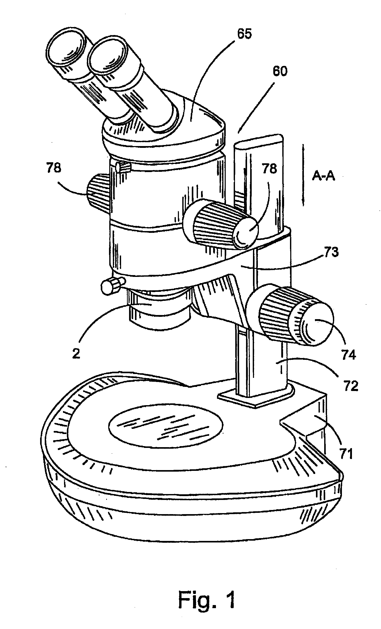
[0048]FIG. 1 is a perspective view of a stereomicroscope 60 according to the prior art. The stereomicroscope 60 comprises a base 71, to which a focusing column 72 is secured. A focusing arm 73 is attached in a displaceable manner to the focusing column 72, which can be displaced via adjustment element 74 along the double arrow A-A. The stereomicroscope 60 has a binocular tube 65 and a zoom system (see FIG. 2). The zoom system can be adjusted with adjusting elements 78.

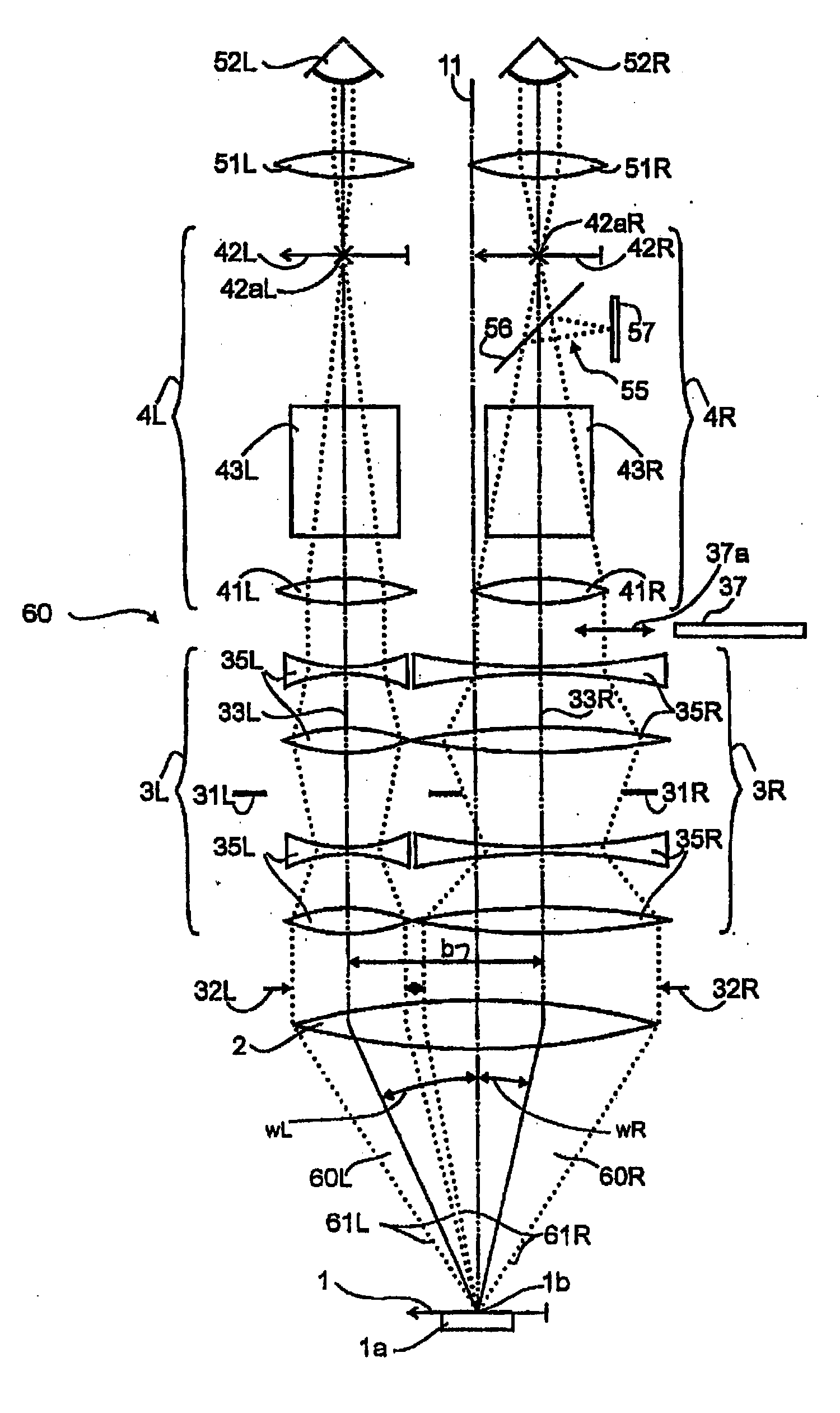
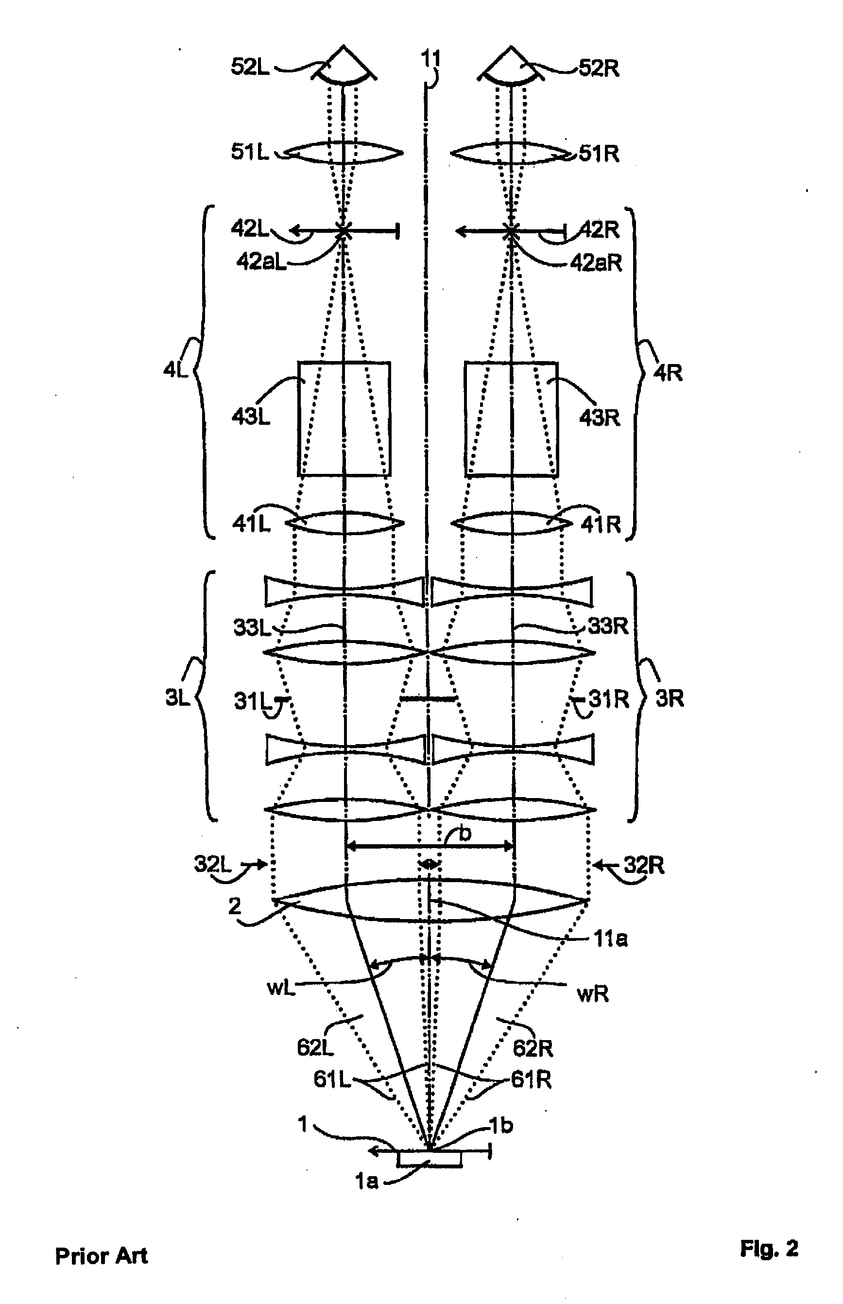
[0049]FIG. 2 is a schematic diagram of the optical design of a stereomicroscope of the telescope type according to the prior art (see DE 102 25 192 B4). The object plane 1 is in the front focal plane of the main objective 2. The object 1a to be investigated or observed is also located in the object plane. In the object plane 1 the object centre 1b is marked by the vertical line 11. The optical axis 11a of the objective 2 coincides with the vertical line 11. In the following the embodiment of the design of the optical ...


PUM


Abstract

A stereomicroscope of the telescope type includes a first beam path and a second beam path, wherein in the first beam path a first telescope system and in the second beam path a second telescope system are provided, wherein the magnifications of both telescope systems are equal and can be changed synchronously to each other, and wherein a common main objective is allocated to both beam paths. In order to increase the resolution without loss in depth of field, it is proposed that at least one optical element of the first telescope system has, compared to at least one corresponding optical element of the second telescope system, a different optically effective diameter.

Description

[0001] Priority is claimed to German Patent Application No. DE 10 2005 040 472.3, filed Aug. 26, 2005, and to German Patent Application No. DE 10 2006 036 300.0, filed on Aug. 3, 2006, both of which are incorporated by reference herein. [0002] The present invention relates to a stereomicroscope. The stereomicroscope can be designed according to Greenough with in each case one objective per stereo channel or as a telescope type with a main objective common for both stereo channels. The stereomicroscope is detachably connected to a focusing arm or incorporated in this. BACKGROUND [0003] Stereomicroscopes are used to manipulate objects under visual observation and / or to make fine object details visible. The object manipulation preferably takes place under low magnification and requires good 3D reproduction. For detail recognition rapid switching to high magnifications with high resolution is desired without change of instrument. [0004] Stereomicroscopes provide two views of the object ...

Claims


Application Information

Patent Timeline
IPC IPC(8): G02B21/22
CPCG02B21/361G02B21/22G02B27/0075
Inventor ZIMMER, KLAUS-PETERROTTERMANN, RUEDISCHNITZLER, HARALD
Owner LEICA INSTR SINGAPORE PTE
Why Eureka
Try Eureka