Minimally invasive bone miller apparatus

a bone miller and minimally invasive technology, applied in the field of artificial joint prostheses, can solve the problems of reducing the size of the incision, and reducing the risk of fracture during broaching

Active Publication Date: 2010-08-31
DEPUY PROD INC
View PDF86 Cites 19 Cited by
  • Summary
  • Abstract
  • Description
  • Claims
  • Application Information

AI Technical Summary

Benefits of technology

[0002]For implantation of prosthetic stems, such as hip stems, accurate preparation of the bone or intramedullary canal is extremely important in order to guarantee good contact between the prosthesis stem and the bone. The underlying concept behind precise preparation is that a precise bone envelope reduces the gaps between the implant (i.e. prosthesis or prosthetic component) and the bone, thereby improving the initial and long-term bone ingrowth / fixation. The bone canal is presently prepared for implantation of a prosthetic stem by drilling and reaming a resected end of a bone, such as a femur, and then preparing an area adjacent the drilled hole to provide a seat for the prosthetic stem or a proximal sleeve coupled to the stem of a modular prosthetic system.
[0006]A standard triangle miller system typically includes a miller shell, a miller frame and a miller cutter having an end formed for coupling to a drill. A typical miller frame and miller cutter can be seen in U.S. Pat. No. 5,540,694 issued to DeCarlo, Jr. et al. on Jul. 30, 1996. This miller frame allows for precise machining of the triangular canal by a miller cutter held at an angle with respect to the shaft of the frame. The triangular canal facilitates an accurate fit of a proximal sleeve that distributes the load experienced by the prosthesis evenly and provides rotational stability. However, to accommodate this miller, it is necessary to make a fairly large incision which may be undesirable for cosmetic or other reasons.
[0014]The disclosed triangular miller is configured to reduce the size of incision required for preparation of a bone with a reamer or milling tool to receive a prosthetic stem therein. The disclosed triangular miller frame includes one or more of the following features, either alone or in combination. A drive shaft alignment bracket supporting a drive shaft. A constant velocity joint at the interface between the drive shaft and the milling tool or reamer facilitating various drive shaft angles. A spring loaded sleeve surrounding portions of the drive shaft to protect soft tissue adjacent to the bone being prepared.

Problems solved by technology

Broaches or rasps, when used for bone preparation, have limitations.
One such limitation is the risk of fracture during broaching.
Since broaching is done by pounding the broach into the bone, the bone tends to fracture.
Additionally, both broaches and rasps suffer from a tendency to be deflected by harder sections of bone so that they do not create as precise a triangular cavity as can be created by a miller system.
A limitation of milling systems today is that they are typically formed so that the drive shaft extends at an angle relative to the remainder of the frame from the end of the miller cutter machining the bone.
However, to accommodate this miller, it is necessary to make a fairly large incision which may be undesirable for cosmetic or other reasons.
Therefore, not only is the input power direction restricted, but this, in turn, restricts the angle at which the reamer may be used on a patient.

Method used


Image

  • Minimally invasive bone miller apparatus
  • Minimally invasive bone miller apparatus
  • Minimally invasive bone miller apparatus

Examples


Embodiment Construction

[0033]For the purposes of promoting an understanding of the principles of the invention, reference will now be made to the embodiments illustrated in the drawings and described in the following written specification. It is understood that no limitation to the scope of the invention is thereby intended. It is further understood that the present invention includes any alterations and modifications to the illustrated embodiments and includes further applications of the principles of the invention as would normally occur to one skilled in the art to which this invention pertains.

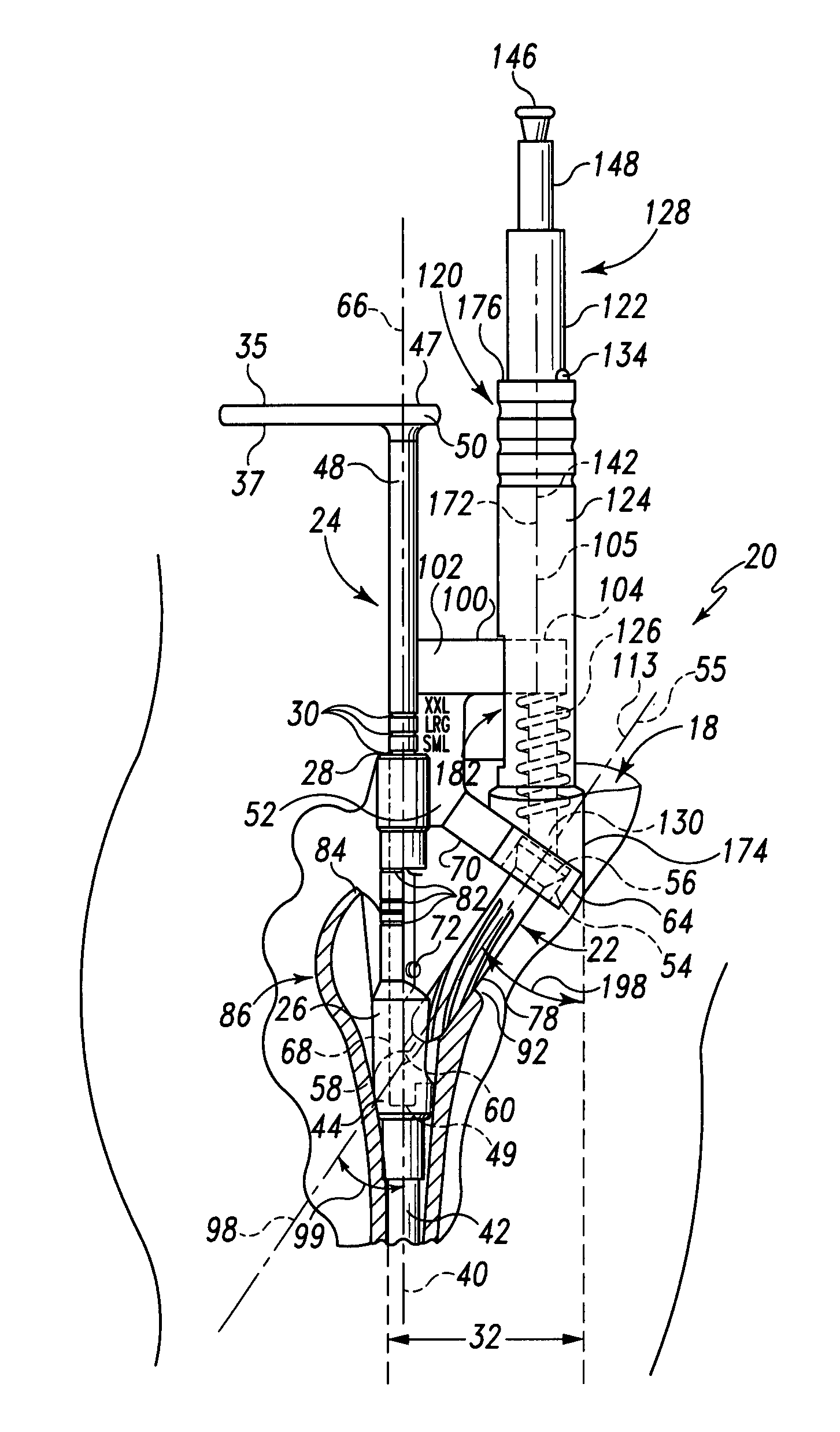
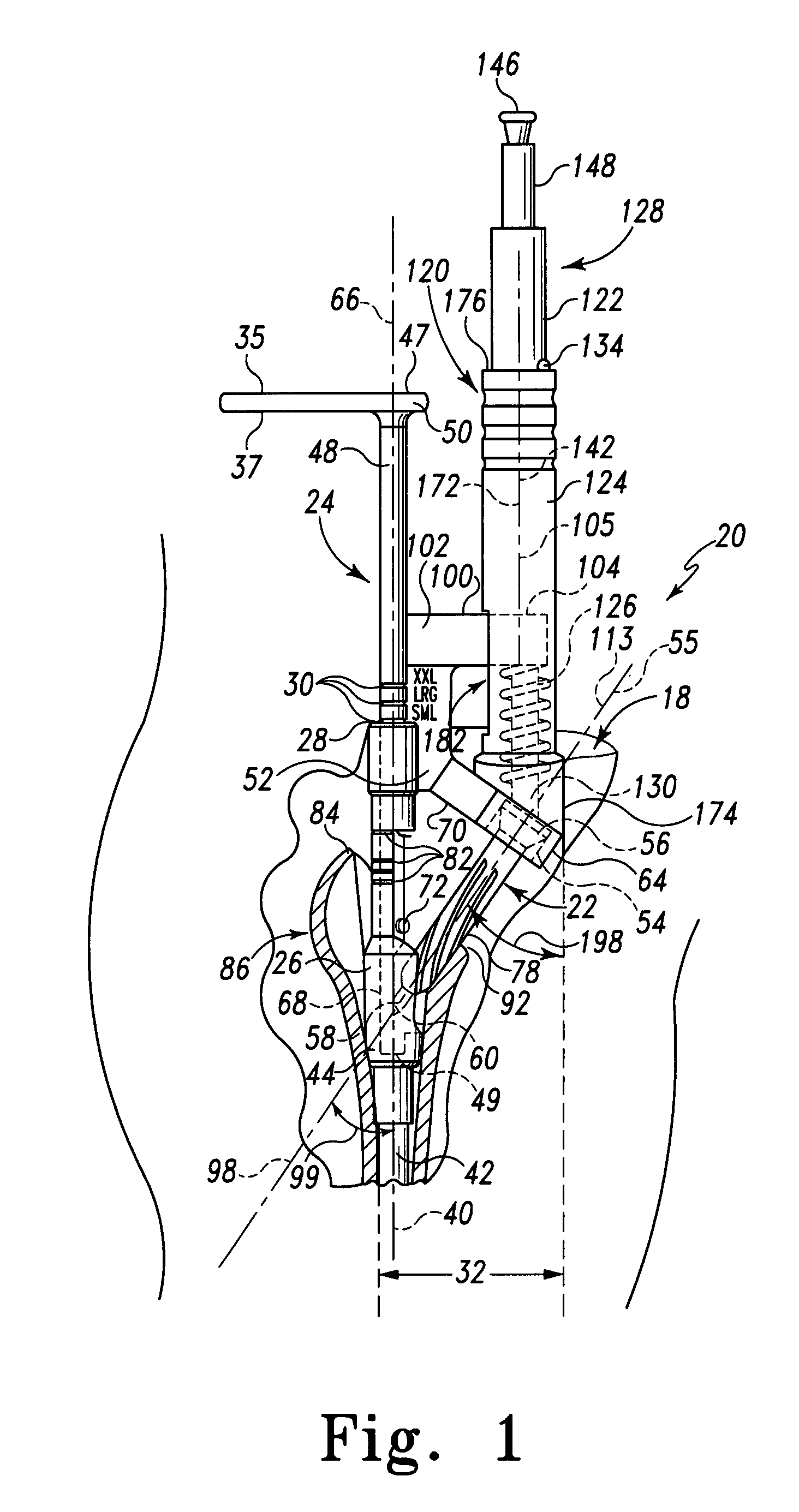
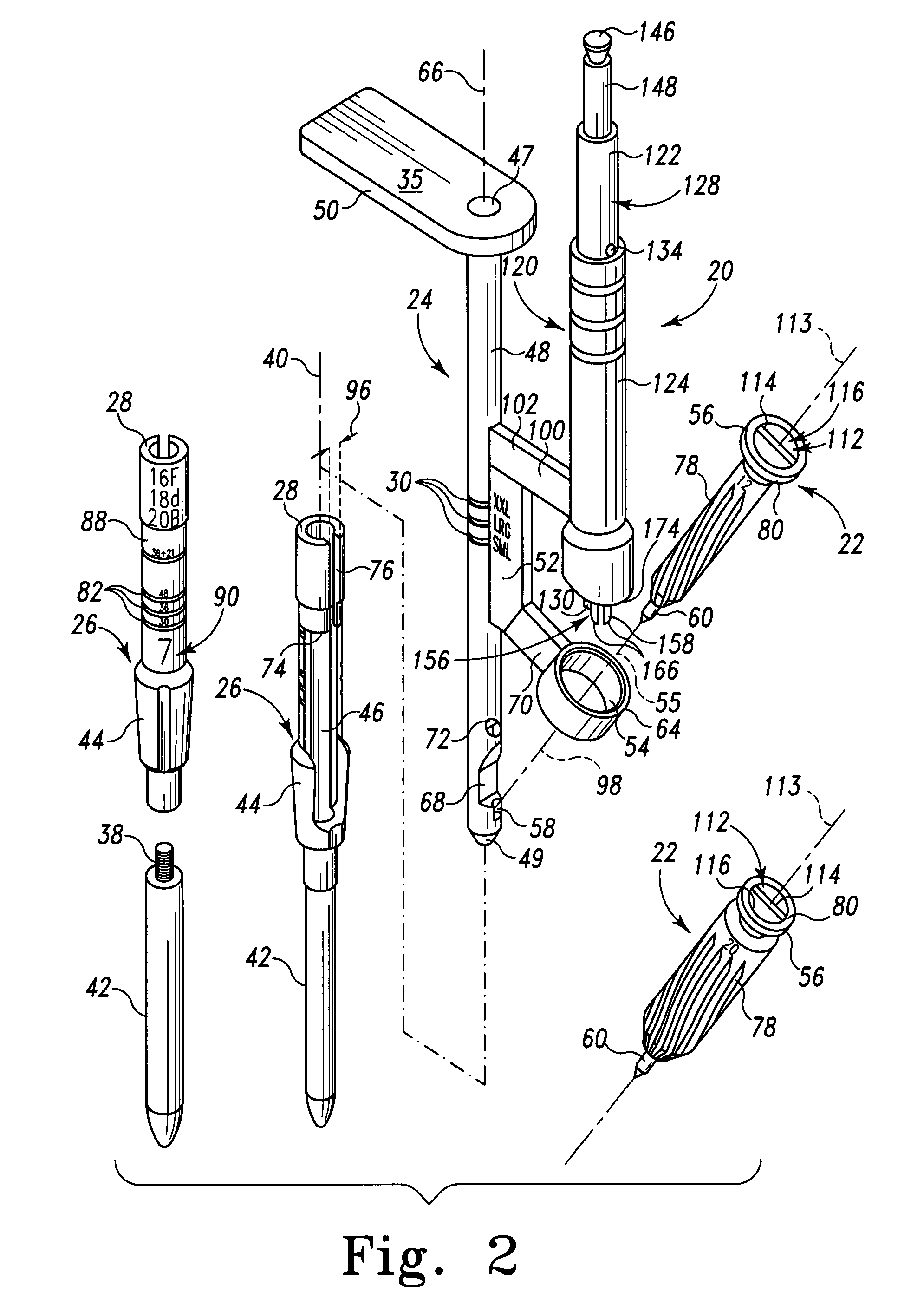
[0034]The disclosed triangle miller assembly 20 allows a surgeon to machine (mill) bone through a smaller incision 18 compared to existing surgical instruments. The disclosed miller assembly 20 is derived from a standard miller assembly such as that disclosed in DeCarlo, Jr. et al., Instrument for Cutting Bone, U.S. Pat. No. 5,540,694, issued Jul. 30, 1996, the disclosure of which is hereby incorporated herein b...


PUM


Abstract

A milling system for creating a cavity in a bone includes a drive shaft, a frame for carrying a cutter and a cutter for cutting the cavity. The drive shaft has a proximal end and a distal end forming a portion of a drive joint for coupling the drive shaft to a cutter. The frame includes a frame shaft and a cutter mount, mounting a cutter at a first angle. The mount includes a bearing bracket extending laterally from the frame shaft to a bearing receiving a portion of a cutter and maintains the received cutter oriented at the first angle during rotation. The cutter has a head forming a portion of drive joint for coupling the cutter to a drive shaft. The cutter is received in the mount at the first angle and the drive shaft forms a second angle with the longitudinal axis less than the first angle.

Description

BACKGROUND AND SUMMARY[0001]This invention relates to the field of artificial joint prostheses and, in particular, to an improved instrument for machining a precise cavity in bone for receiving a prosthesis.[0002]For implantation of prosthetic stems, such as hip stems, accurate preparation of the bone or intramedullary canal is extremely important in order to guarantee good contact between the prosthesis stem and the bone. The underlying concept behind precise preparation is that a precise bone envelope reduces the gaps between the implant (i.e. prosthesis or prosthetic component) and the bone, thereby improving the initial and long-term bone ingrowth / fixation. The bone canal is presently prepared for implantation of a prosthetic stem by drilling and reaming a resected end of a bone, such as a femur, and then preparing an area adjacent the drilled hole to provide a seat for the prosthetic stem or a proximal sleeve coupled to the stem of a modular prosthetic system.[0003]Modular pros...

Claims


Application Information

Patent Timeline
Patent Type & Authority Patents(United States)
IPC IPC(8): A61B17/00A61B17/56A61B17/16A61B17/17A61B19/00A61F2/36
CPCA61B17/1668A61B17/1631A61B17/1675A61B17/1684A61B2019/461A61F2/367A61B2090/061
Inventor CHRISTIE, MICHAEL JDEBOER, DAVID K.JONES, MICHAEL C.SMITH, STEVEN WAYNEPARKER, BRAD ALANJAGGERS, CHARLES W.SHRACK, DEREK A.ROGERS, JAMES RAY
Owner DEPUY PROD INC
Why Eureka
Try Eureka