Folding mechanism of a treadmill

Inactive Publication Date: 2010-09-07
WANG LEAO
View PDF7 Cites 14 Cited by
  • Summary
  • Abstract
  • Description
  • Claims
  • Application Information

AI Technical Summary

Benefits of technology

[0006]A primary object of the invention is to provide a folding mechanism of a treadmill having a base frame supported by the pneumatic cylinder. In folding the treadmill upward or downward, the pneumatic cylinder provides both an auxiliary force and a support force acting on the rear support frame. Meanwhile, the rear end of the rear support frame is provided with universal ground-touching rollers that serves as auxiliaries for a practical movement of the treadmill and an easy change in direction
[0007]According to the invention, a folding mechanism of a treadmill has a base frame with a rear support frame at the bottom thereof. The rear support frame is supported by the pneumatic cylinder. In folding the treadmill upward or downward, the rear support frame can be pushed by the pneumatic cylinder such that the base frame is easily brought in an upright storage position or in a horizontal operation position. Moreover, the rear end of the rear support frame is provided with universal ground-touching rollers that may be locked in place or unlocked for a practical movement of the treadmill and an easy change in direction.

Problems solved by technology

As well-known, the conventional treadmill has a large volume and a great weight.
Among the conventional treadmills, they can't properly provide an auxiliary force and a support force when the base frame of the treadmill is folded or unfolded (in an operational position).
In other words, there are no devices (in the conventional treadmills with the manual folding mechanism) for giving the operator aid in conducting the folding action.
It is therefore unsuitable for those who has a weak physical condition or for women to carry out the folding or unfolding process by themselves.
Actually, the potential risk to cause the body injuries exists.

Method used


Image

  • Folding mechanism of a treadmill
  • Folding mechanism of a treadmill
  • Folding mechanism of a treadmill

Examples


Embodiment Construction

[0016]The present invention will now be described in more detail hereinafter with reference to the accompanying drawings that show various embodiments of the invention.

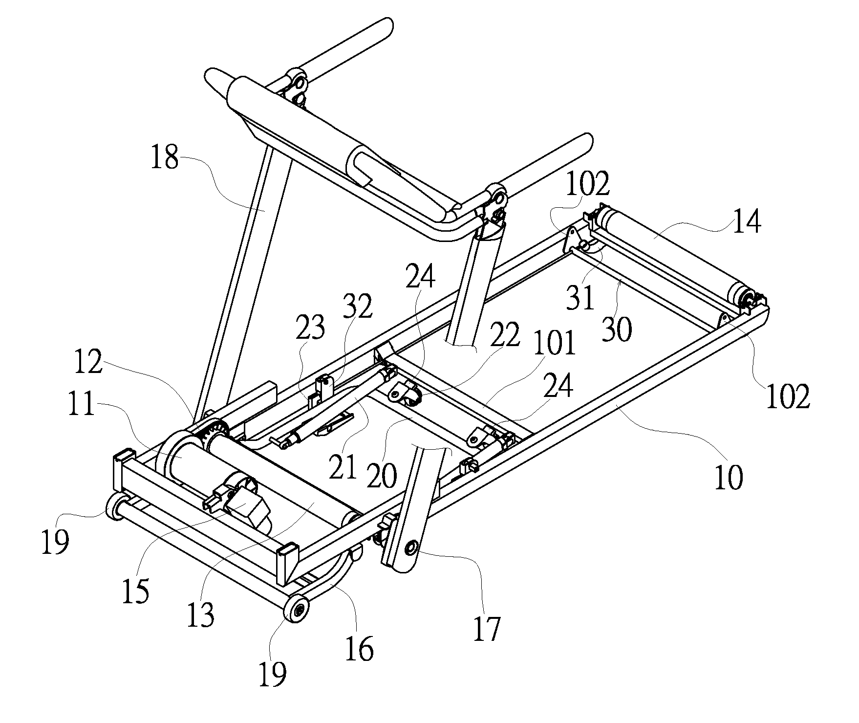
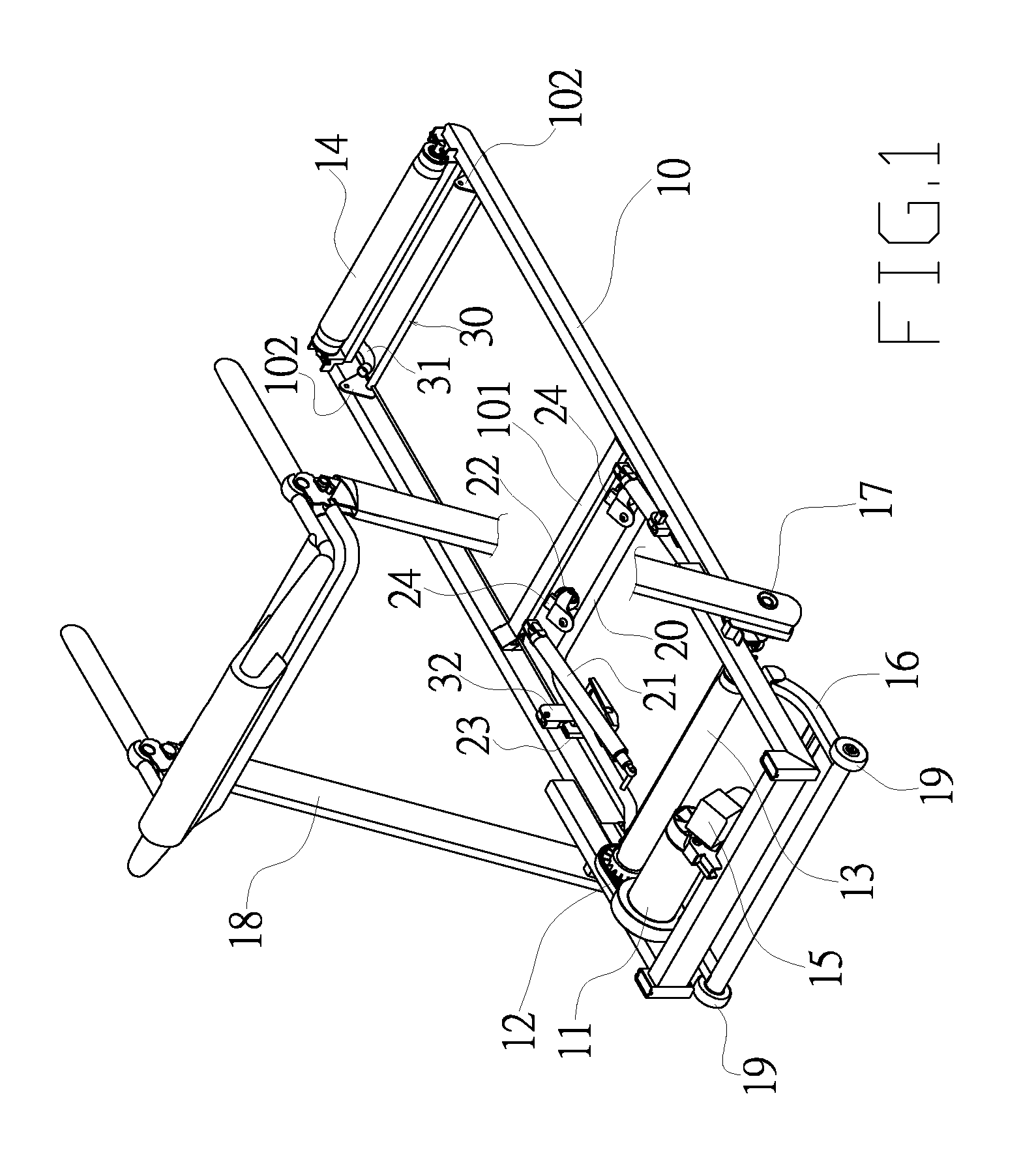
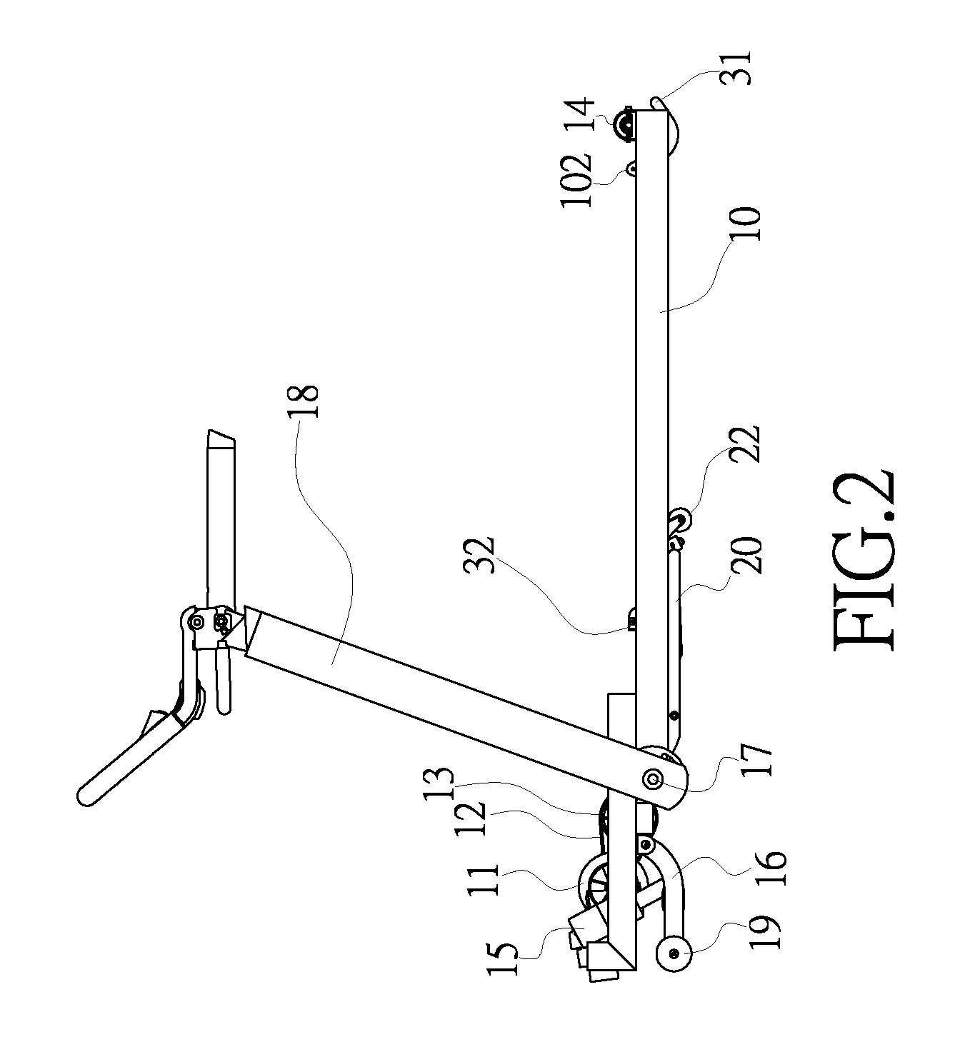
[0017]Referring to FIGS. 1 through 3, a drive motor unit 11 is installed at one side of a base frame 10 of a treadmill. A continuous moving belt (not shown) is driven in rotation by use of a drive belt 12, a front roller 13 and a rear roller 14. Moreover, a lifting motor 15 is employed to control the height of an adjusting support 16 for adjusting the supporting angle of the base frame 10. In addition, a mounting pin 17 is positioned at each of two sides of the base frame 10 for pivotally connecting a handrail unit 18 and a rear support frame 20.

[0018]Besides, a pneumatic cylinder 21 is installed at each of two sides of a central strengthening rod 101 of the base frame 10. The other side of the pneumatic cylinder 21 is directly pushed against a corresponding portion of the rear support frame 20. The distal end of the ...


PUM


Abstract

A folding mechanism of a treadmill having a base frame with a rear support frame at the bottom thereof. The rear support frame is supported by the pneumatic cylinder. In folding the treadmill upward or downward, the rear support frame can be pushed by the pneumatic cylinder such that the base frame is easily brought in an upright storage position or in a horizontal operation position. Moreover, the rear end of the rear support frame is provided with universal ground-touching rollers that may be locked in place or unlocked for a practical movement of the treadmill and an easy change in direction.

Description

BACKGROUND OF THE INVENTION[0001]1. Fields of the Invention[0002]The invention relates to a folding mechanism of a treadmill, and more particularly, to a folding mechanism that properly provides both an auxiliary force and a support force when the base frame of the treadmill is folded or unfolded. Meanwhile, a practical movement of the treadmill and an easy change in direction are effectively achieved as well.[0003]2. Description of the Related Art[0004]As well-known, the conventional treadmill has a large volume and a great weight. As a result, the base frame thereof is designed to be foldable in a upright position for an easy movement and a practical storage. Of course, the folding structure has been a basic design of the treadmill. Moreover, it can be roughly divided into an electric and a manual folding mechanism. The invention is aimed at the improvement of the manual folding mechanism.[0005]Among the conventional treadmills, they can't properly provide an auxiliary force and a...

Claims


Application Information

Patent Timeline
IPC IPC(8): A63B22/02
CPCA63B22/0235A63B22/0023A63B2071/0063A63B2071/025A63B2210/50
Inventor WANG, LEAO
Owner WANG LEAO
Why Eureka
Try Eureka