Electronic apparatus, method for controlling electronic apparatus, and non-transitory computer readable storage medium

Pending Publication Date: 2022-10-13
CANON KK
View PDF0 Cites 0 Cited by
  • Summary
  • Abstract
  • Description
  • Claims
  • Application Information

AI Technical Summary

Benefits of technology

The present invention allows the user to easily direct their line of vision to a specific area. This simplifies the user's task and improves their overall performance.

Problems solved by technology

When a GUI image is displayed in an area other than an area desired by the user (the area the user wishes to see) in obtaining the user's line of vision position, the user's line of vision tends to be directed to the displayed GUI image, and it is difficult to keep the line of vision in the desired area.

Method used


Image

  • Electronic apparatus, method for controlling electronic apparatus, and non-transitory computer readable storage medium
  • Electronic apparatus, method for controlling electronic apparatus, and non-transitory computer readable storage medium
  • Electronic apparatus, method for controlling electronic apparatus, and non-transitory computer readable storage medium

Examples


embodiment

Tracking Processing Using Viewpoint (Embodiment)

[0056]FIG. 8 is a flowchart for illustrating exemplary tracking processing according to the embodiment. Processing steps in the flowchart are carried out when the CPU 3 executes the program stored in the memory unit 4. According to the embodiment, the processing in this flowchart starts when the power supply of the camera is turned on.

[0057]In step S801, when the power supply of the camera is turned on and the image-sensing device 2 starts to obtain a through image (an input image), the CPU 3 starts to display the through image on the display device 10. According to the embodiment, the user visually recognizes the subject by viewing the through image displayed on the display device 10 in the view finder.

[0058]In step S802, the CPU 3 determines whether the line of vision input is on. According to the embodiment, the CPU 3 determines that the line of vision input is on when the line-of-vision detecting function (the line of vision input ...

second embodiment

[0079]In the description of the first embodiment, the line-of-vision GUI is always displayed, except when the position of the subject GUI and the line of vision position overlap, while according to this embodiment, the line-of-vision GUI is displayed only when tracking processing is performed using the line-of-vision information by way of illustration.

[0080]FIG. 10 is a flowchart for illustrating exemplary tracking processing according to the embodiment. Processing steps in this flowchart are carried out as the CPU 3 executes a program stored in the memory unit 4. According to the embodiment, the processing in the flowchart starts when the power supply of the camera is turned on. The same processing steps as those shown in FIG. 8 are indicated by the same reference numbers and their description will not be provided.

[0081]According to the embodiment, steps S804 to S806 shown in FIG. 8 are not performed, and therefore the processing of displaying or hiding the line-of-vision GUI is no...

third embodiment

[0087]In the above description of the embodiment, the line-of-vision information is used by way of illustration when tracking a moving object, while in the following description of this embodiment, the line-of-vision information is used when detecting a face.

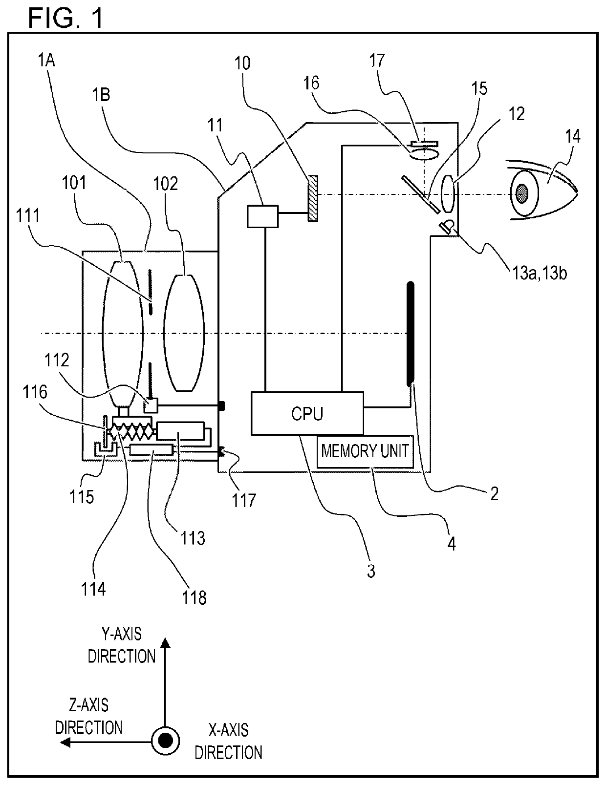
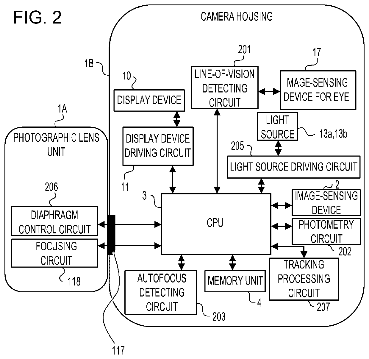
[0088]FIG. 12 is a block diagram of the electrical configuration in the camera 1 according to the embodiment. In FIG. 12, a face detecting circuit 208 is provided instead of the tracking processing circuit 207 in FIG. 2.

[0089]Using template data on a human face stored in the memory unit 4 in advance, the face detecting circuit 208 detects, as a face image, the part (area) of the frame image having similarity to the template which exceeds a reference value. The face detecting method is not limited to the above, and various known techniques can be applied.

[0090]FIG. 13 is a flowchart for illustrating the face detecting processing according to the embodiment. Processing steps in the flowchart are carried out as the CPU 3 executes a...


PUM


Abstract

An electronic apparatus includes: a display control unit configured to display an input image, a first GUI image, and a second GUI image at a display; a first detecting unit configured to detect a position of a predetermined object in the input image; and a second detecting unit configured to detect a viewpoint of a user in the input image, wherein the display control unit displays the first GUI image in a position corresponding to the position of the predetermined object detected by the first detecting unit and the second GUI image in a position corresponding to the viewpoint detected by the second detecting unit, and in a case where the first GUI image and the second GUI image overlap, the display control unit makes the second GUI image less noticeable than in a case where the first GUI image and the second GUI image do not overlap.

Description

CROSS-REFERENCE TO RELATED APPLICATIONS[0001]This application is a Continuation of International Patent Application No. PCT / JP2020 / 028738, filed Jul. 27, 2020, which claims the benefit of Japanese Patent Application No. 2019-162729, filed Sep. 6, 2019, both of which are hereby incorporated by reference herein in their entirety.BACKGROUND OF THE INVENTIONField of the Invention[0002]The present invention relates to an electronic apparatus, a method for controlling an electronic apparatus, and a non-transitory computer readable storage medium.Background Art[0003]In recent years, cameras have become more automated and intelligent, and techniques for detecting an object intended by the user on the basis of information about the line of vision position of the user looking into the view finder (line-of-vision information; line of vision input information) and performing focus control without manually inputting the position of the object have been proposed. PTL 1 discloses a technique for i...

Claims


Application Information

Patent Timeline
IPC IPC(8): H04N5/232G06T7/70G06T7/20G06V40/16H04N5/262G06V40/18
CPCH04N5/232935G06T7/70G06T7/20G06V40/161H04N5/2628H04N5/23219G06V40/18G06T2200/24G06T2207/30201G09G3/20G09G3/001G09G2310/04G09G2320/0686G09G2354/00G06F3/013G06T7/73G06T7/248G06T2207/30196G06T2207/10048H04N23/67H04N23/611H04N23/631H04N23/635H04N23/71H04N23/51H04N23/55H04N23/54H04N25/71H04N23/632
Inventor SAKATO, KAZUMAKATAGAWA, HIROYASU
Owner CANON KK
Why Eureka
Try Eureka