Light mounting apparatus

Inactive Publication Date: 2011-01-18
HANCHETT NEVILLE BLAKE
View PDF18 Cites 5 Cited by
  • Summary
  • Abstract
  • Description
  • Claims
  • Application Information

AI Technical Summary

Benefits of technology

[0013]A light mounting apparatus is being proposed herein. The light mounting apparatus is formed to as to allow for versatile usage, in connection with a wide variety of tools, structures, and surfaces. Furthermor

Problems solved by technology

However, significant problems arise when attempting to attach a device in this manner.
None of these patents provide a device t

Method used


Image

  • Light mounting apparatus
  • Light mounting apparatus
  • Light mounting apparatus

Examples


Example

DETAILED DESCRIPTION OF THE FIGURES

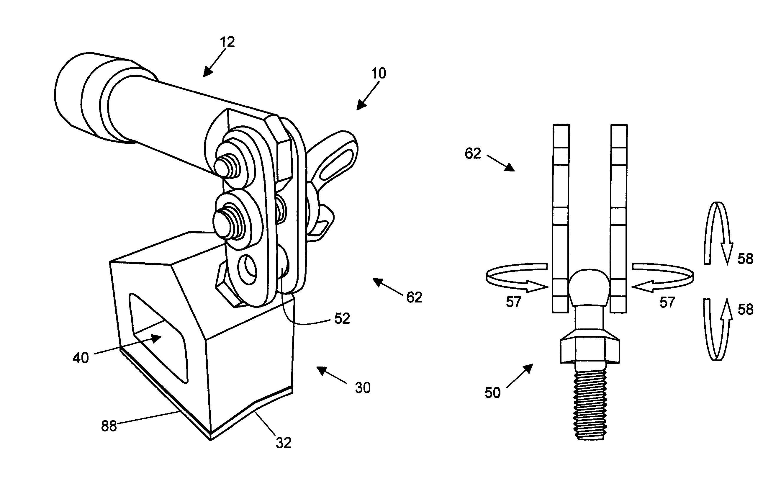
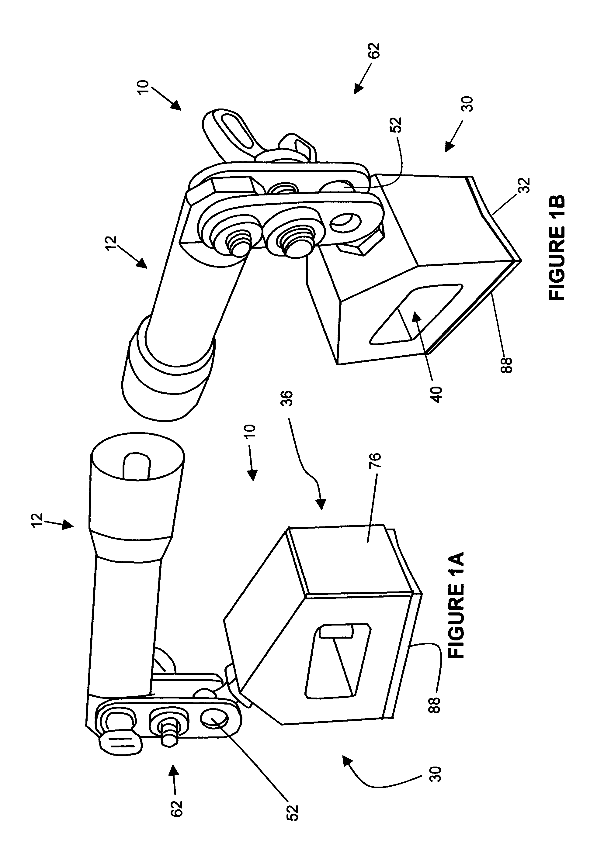
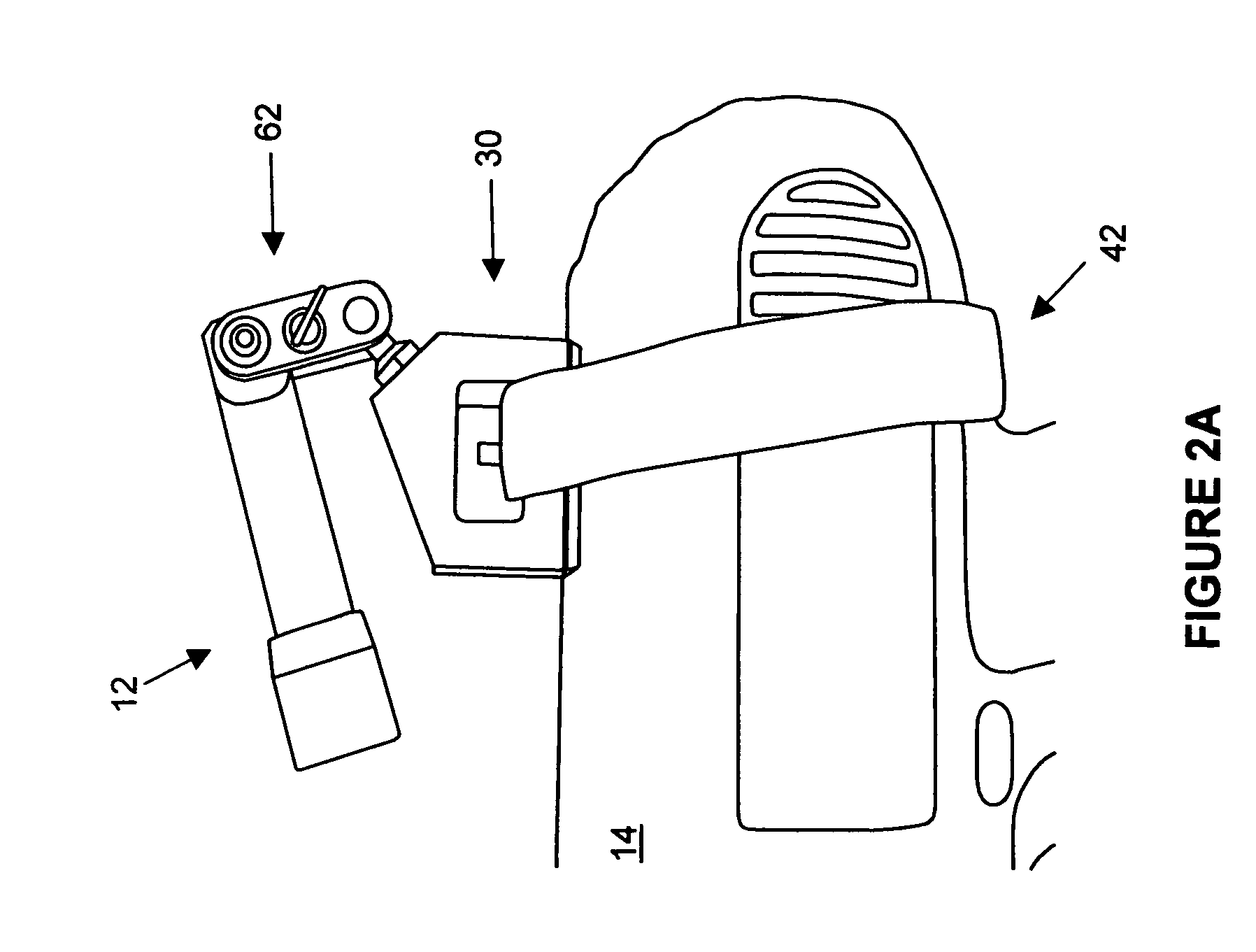
[0041]A light mounting apparatus is being proposed herein. The light mounting apparatus is formed to as to allow for versatile usage, in connection with a wide variety of tools, structures, and surfaces. Furthermore, the light mounting apparatus includes suitable connection structures to a light source in order to provide multiple degrees of freedom, thereby allowing a user to easily direct light beams to a desired location.

[0042]In certain embodiments, the light mounting apparatus allows one to easily attach and detach it at various locations on a tool, thereby affording the ability to position a light source (e.g., a conventional pocket flashlight) and direct a light beam from the light source on a desired position of a workpiece. In certain additional embodiments, the light mounting apparatus may be easily attached and detached to a variety of structures, e.g., within a home, workshop, or automobile, whereby a user may direct light to a desired ...


PUM


Abstract

A light mounting apparatus is being proposed herein. The light mounting apparatus is formed to as to allow for versatile usage, in connection with a wide variety of tools, structures, and surfaces. Furthermore, the light mounting apparatus includes suitable connection structures to a light source in order to provide multiple degrees of freedom, thereby allowing a user to easily direct light beams to a desired location.

Description

RELATED APPLICATIONS[0001]This application is related to and claims priority from U.S. Provisional Patent Application Ser. No. 61 / 001,512 filed Nov. 1, 2007 which is incorporated by reference herein.TECHNICAL FIELD[0002]This invention relates generally to the field of light mounting apparatus, and more particularly to light mounting apparatus suitable for attachment to a variety of tools, structures and / or surfaces.BACKGROUND ART[0003]U.S. Pat. Nos. 5,573,329 and 5,683,171 shows an example whereby a cylindrical unit is supposedly strapped to a drill to direct a light beam to a workpiece or the like. However, significant problems arise when attempting to attach a device in this manner. Various attempts to solve this problem have been attempted:[0004]U.S. Pat. No. 5,303,133 shows a light mounting structure for a fishing pole;[0005]U.S. Pat. No. 5,797,670 shows a belt where light focus is adjusted by a gooseneck structure;[0006]U.S. Pat. No. 6,186,638 shows a wrench with a flashlight; ...

Claims


Application Information

Patent Timeline
IPC IPC(8): F21V33/00
CPCB25B23/18B25F5/021F21V21/0885F21V33/0084
Inventor HANCHETT, NEVILLE BLAKE
Owner HANCHETT NEVILLE BLAKE
Why Eureka
Try Eureka