
Racking of electrical distribution devices

a technology of electrical distribution device and rack, which is applied in the direction of contact, switchgear with a retractable carriage, coupling device connection, etc., can solve the problem of preventing breaker insertion/removal

Active Publication Date: 2010-09-14
ABB SPA
View PDF7 Cites 22 Cited by
  • Summary
  • Abstract
  • Description
  • Claims
  • Application Information

AI Technical Summary

Benefits of technology

The invention is an electrical distribution apparatus that includes a fixed terminal, at least two fingers attached at pivot points, and a mechanical spring that provides tension upon separation of the fingers. The at least two fingers are of different length, and the pivot points are formed between the fixed terminal and each finger. The apparatus can be used in an electrical distribution system with a fixed terminal and terminal length arranged along the footprint of the system. The technical effect of the invention is to provide a compact and efficient electrical distribution apparatus that can be easily installed and maintained.

Problems solved by technology

Thus, if more circuit breakers, or even larger circuit breakers, with differing current limiting requirements and / or thermal requirements are necessary for an application, breaker insertion / removal may be hindered due to large racking forces.

Method used


Image

  • Racking of electrical distribution devices
  • Racking of electrical distribution devices
  • Racking of electrical distribution devices

Examples


Embodiment Construction

[0014]Detailed illustrative embodiments are disclosed herein. However, specific functional details disclosed herein are merely representative for purposes of describing example embodiments. Example embodiments may, however, be embodied in many alternate forms and should not be construed as limited to only the embodiments set forth herein.

[0015]Accordingly, while example embodiments are capable of various modifications and alternative forms, embodiments thereof are shown by way of example in the drawings and will herein be described in detail. It should be understood, however, that there is no intent to limit example embodiments to the particular forms disclosed, but to the contrary, example embodiments are to cover all modifications, equivalents, and alternatives falling within the scope of example embodiments.

[0016]It will be understood that, although the terms first, second, etc. may be used herein to describe various steps or calculations, these steps or calculations should not b...


PUM


Abstract

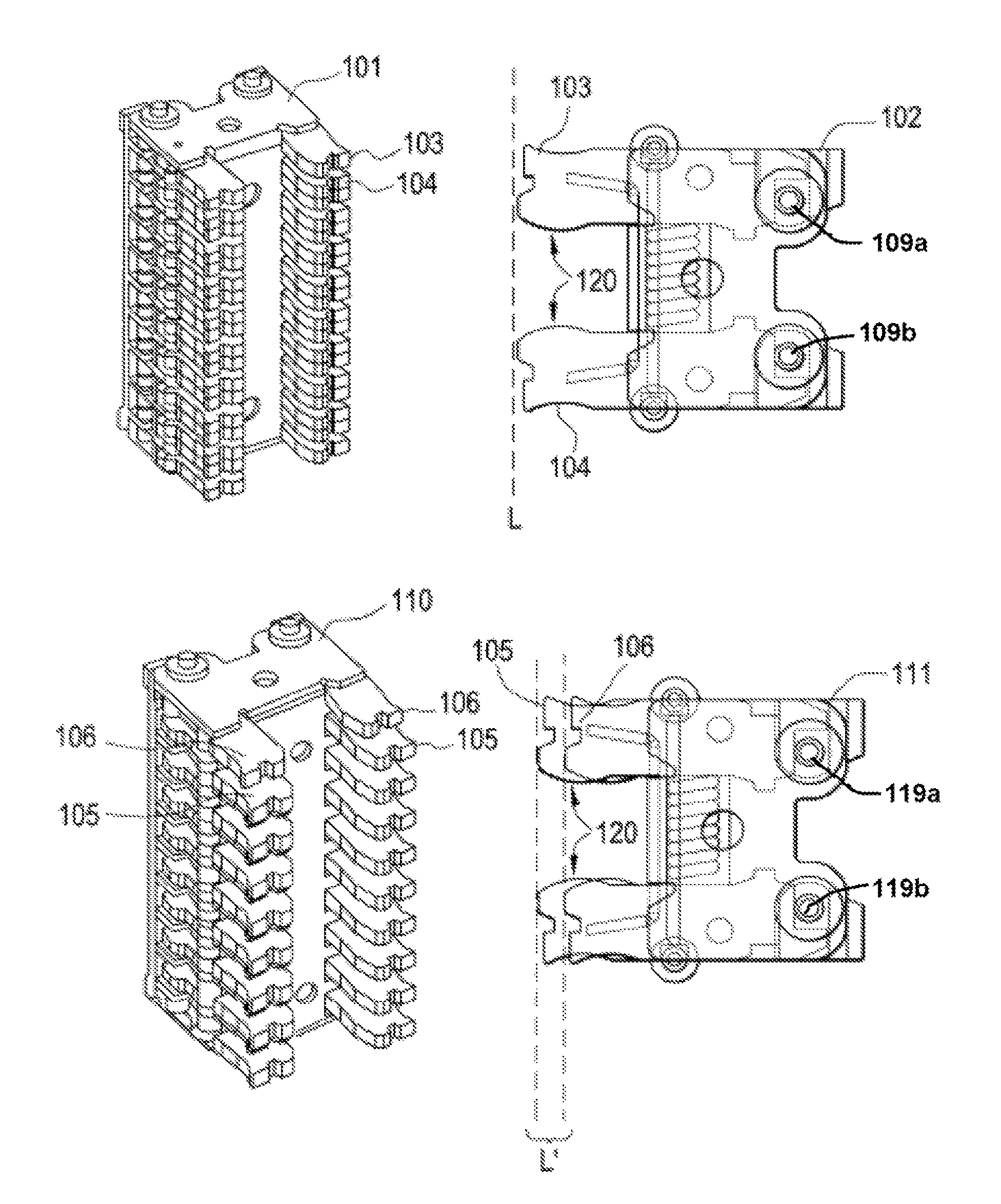
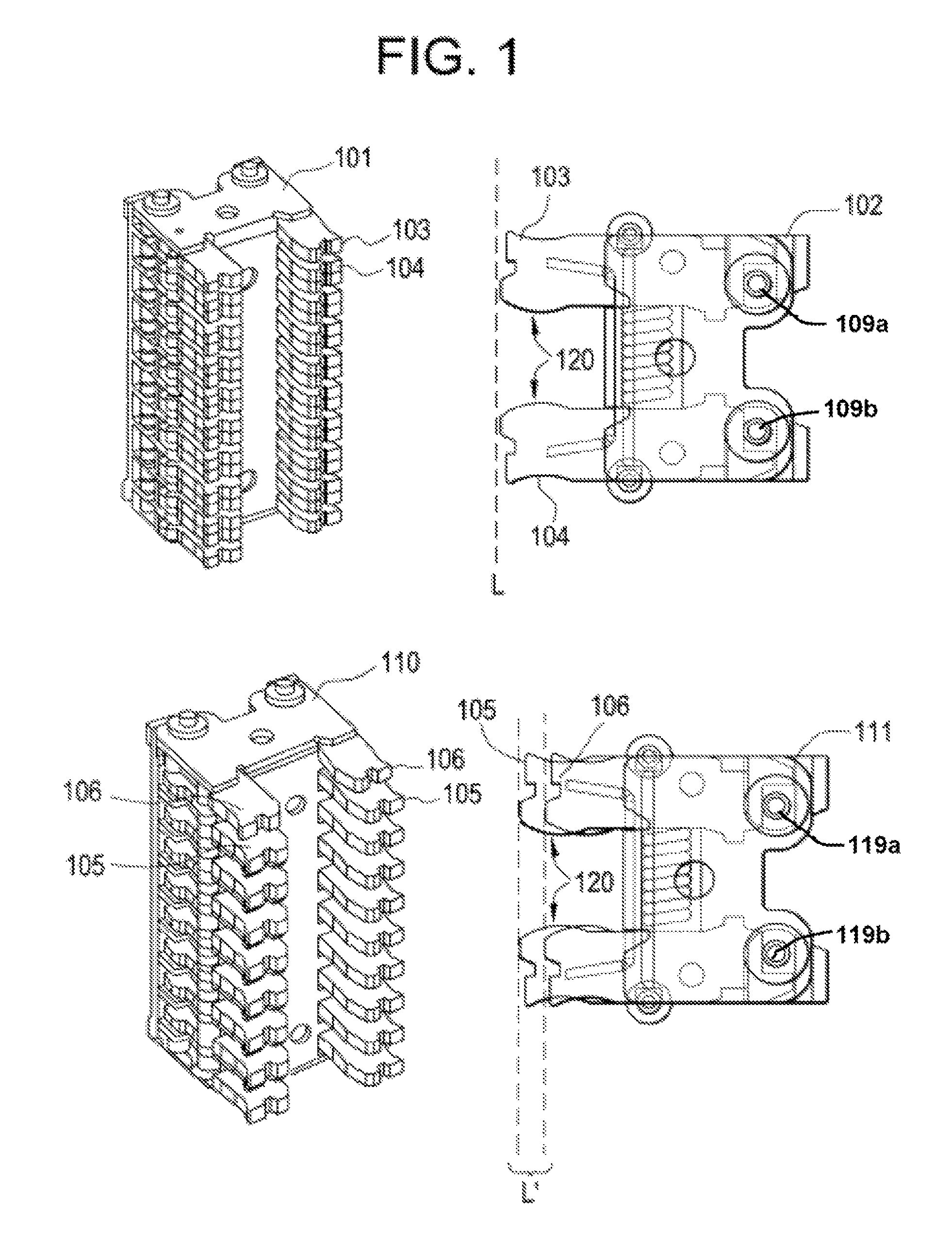
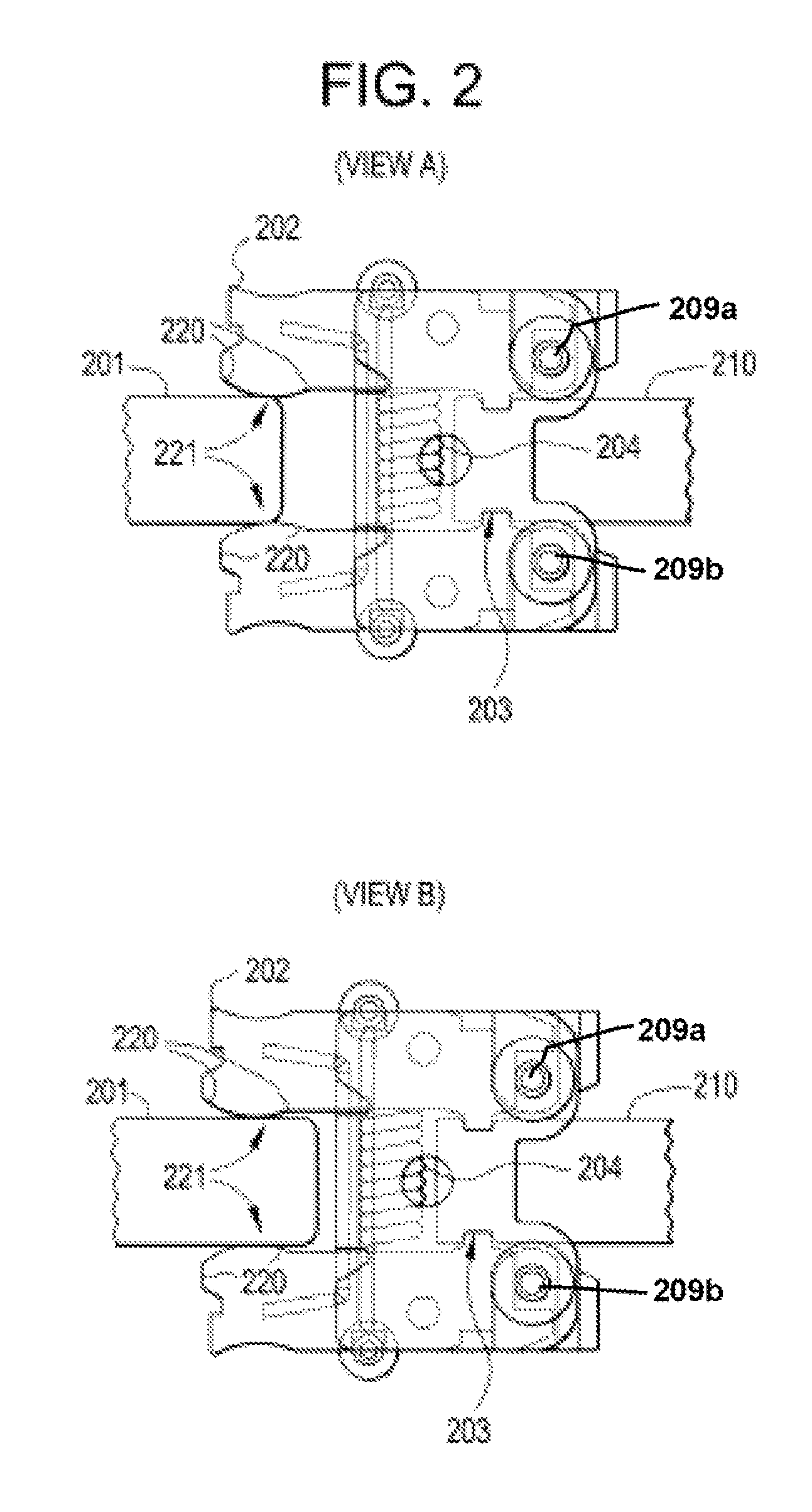
An electrical distribution apparatus includes a fixed terminal, at least two fingers attached at respective pivot points in the apparatus, and a mechanical spring in operative communication with the at least two fingers, configured to provide tension upon separation of the at least two fingers. According to the apparatus, the at least two fingers are of a different length, length is a measure of the distance from a pivot point of a finger to an end of the finger, and the respective pivot points are each formed between the fixed terminal and each of the two fingers.

Description

BACKGROUND OF THE INVENTION[0001]Embodiments of the invention generally relate to electrical distribution devices, and more particularly to racking of electrical distribution devices, for example, circuit breakers.[0002]Conventional electrical distribution equipment generally includes one or more circuit breakers, and often includes a plurality of circuit breakers housed in drawout units in switchgear housings and other electrical equipment. Periodically, the circuit breaker drawout units require removal to facilitate maintenance and or replacement of the associated switching devices. Similarly, additional switching devices may be placed within the drawout units. In order to facilitate placement of additional devices and / or removal of existing devices, the circuit breaker is “racked in” or “racked out,” respectively.[0003]In general, a typical circuit breaker may be connected to the external power source through disconnects termed primary disconnects. The primary disconnects aid in ...

Claims


Application Information

Patent Timeline
Patent Type & Authority Patents(United States)
IPC IPC(8): H01H1/50
CPCH01H1/42H01H2001/425H02B11/04
Inventor NARAYANAN, JANAKIRAMANNEWASE, YATIN VILASDODDAPADAM SRINIVASA RAGHAVACHAR, PARTHA SARATHYNARAYANASAMY, SOUNDARARAJANRANE, MAHESH JAYWANT
Owner ABB SPA
Learn More