
Mooring/vessel snap hook device

a technology for capturing moorings and hooks, which is applied in vessel construction, marine site engineering, construction, etc., can solve the problems of not always easy to capture moorings, many boat operators often have to make several dangerous attempts to capture moorings, and the cable hook is not suitable for quick grasping, so as to achieve safe capturing of chains and ropes.

Inactive Publication Date: 2010-10-12
DUARTE HELDER F +1
View PDF29 Cites 6 Cited by
  • Summary
  • Abstract
  • Description
  • Claims
  • Application Information

AI Technical Summary

Benefits of technology

Enables safe and efficient mooring by allowing the boat operator to capture a chain or rope under a mooring buoy without leaving the cockpit, improving safety and reducing the risk of accidents in rough waters.

Problems solved by technology

The attachment of the line between the mooring buoy and the bow of the boat requires the boat operator to leave a cockpit area and move to the bow area in order to make the mooring line connection to a bow eye or chock which is not always an easy thing to do due in the presence of wind, waves, current, and other nearby boats.
Many boat operators often have to make several dangerous attempts to capture a mooring line of a mooring buoy by hanging off the bow of the boat.
However, this cable hook is not suitable for quickly grasping a chain under a mooring buoy.
However, this assembly does not disclose a coiled spring for opening and closing the hook and does not easily capture a chain under a moving buoy.
However, this device does not comprise a coiled spring for easily grasping a chain under a mooring and is primarily for grasping a mooring loop or ring on top of a mooring.
However, this tool is not designed to grab a chain hanging down to a weight under a mooring buoy.
However, this boat mooring hook is not suitable for grasping a chain under a mooring buoy.

Method used


Image

  • Mooring/vessel snap hook device
  • Mooring/vessel snap hook device
  • Mooring/vessel snap hook device

Examples


Embodiment Construction

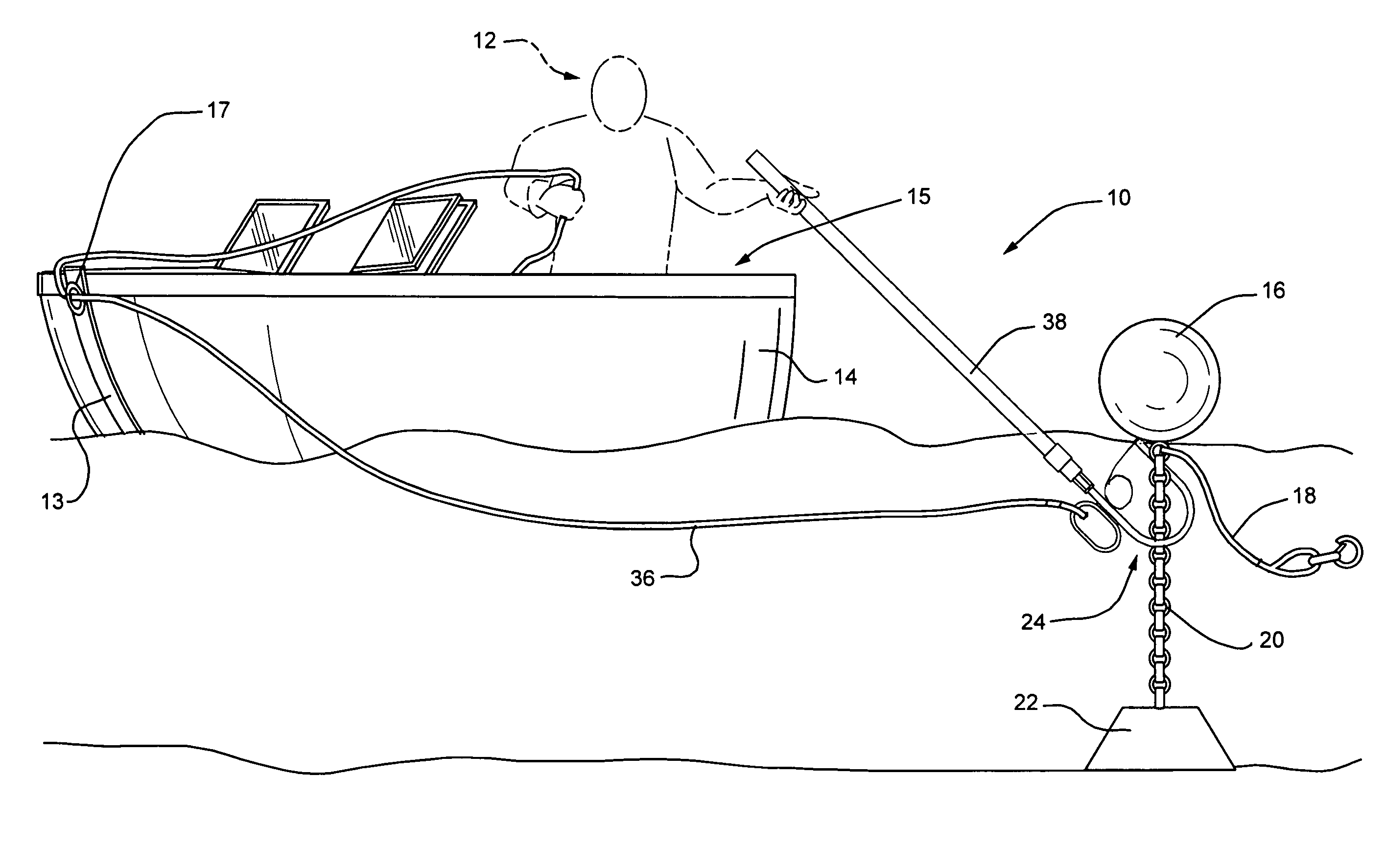
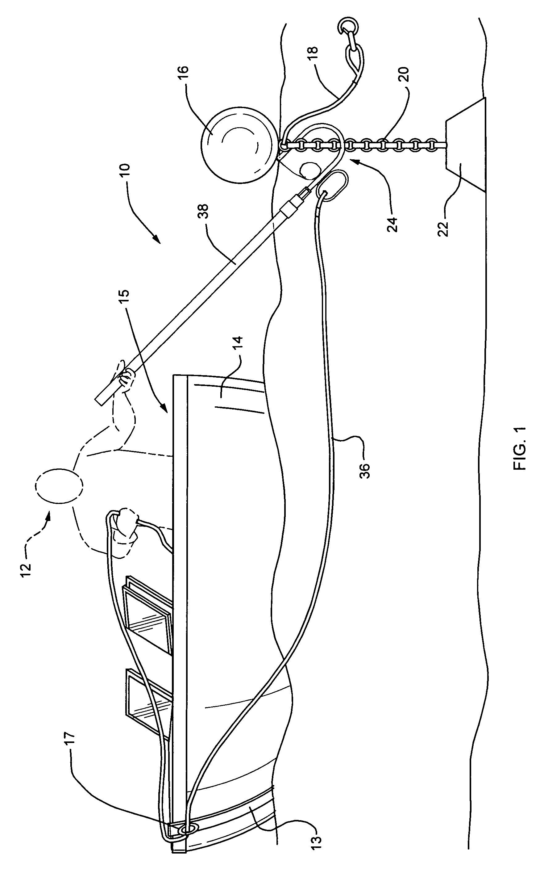
[0028]Referring to FIG. 1, FIG. 1 shows a boat operator 12 in a cockpit area 15 of a boat 14 using a snap hook device 10 according to the present invention to capture A chain 20 attached under a mooring buoy 16 to facilitate bringing a bow 13 of the boat adjacent to the mooring buoy 16 and attaching a mooring rope 18 to a ring 17 or chock on the bow 13 of the boat 14.

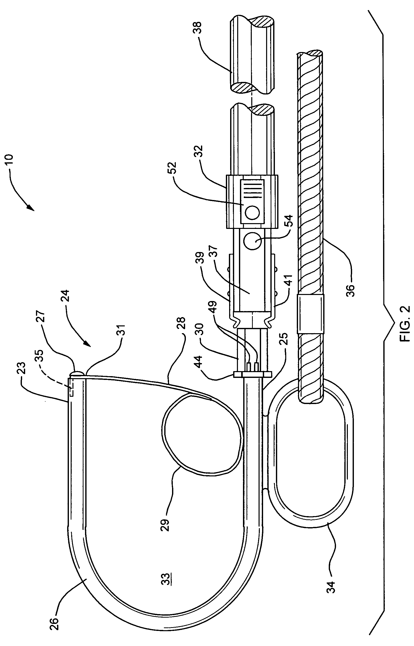
[0029]Referring to FIG. 2, a side elevational view of the snap hook device 10 is shown comprising a U-shaped hook 26, a spring closure 28, a collar 30, a detachable pole 38, a link 34 and a rope 36. The spring closure 28 comprises a 90 degree bend on a first end 31 which fits into a slot 35 in the end 23 of the U-shaped hook 26, and the first end 31 is attached by a screw or bolt 27 to a first or nose end 23 of the U-shaped hook 26. The other end 29 of the spring closure 28 is coiled having a diameter of approximately 1.5 inches and rests against an inside surface of a second or body end 25 of the U-shaped hook 26. The ...


PUM


Abstract

A snap hook device comprises a detachable pole attached to a snap hook having a side link for securing a rope. The snap hook is generally U-shaped with a sloped spring closure having a first end attached to a first end of the hook and a second end of the spring closure being coiled and resting against a side of a second end of the snap hook. The second end of the U-shaped hook comprises a collar for receiving the detachable pole. The snap hook device enables a boat operator when alone in the boat to remain in the cockpit area of the boat, and capture a chain under a mooring buoy. The operator then maneuvers the boat with a rope attached to a link of the snap hook wherein the rope extends via the bow to the boat operator in the cockpit, so that by pulling the rope, the bow is easily and safely turned to be adjacent to the mooring buoy for attaching a mooring line.

Description

BACKGROUND OF THE INVENTION[0001]Field of the Invention[0002]This invention relates generally to a device for capturing a mooring buoy to attach a boat thereto and, in particular, to a snap hook device for capturing a chain under the mooring buoy from the safety of the boat's cockpit and being able to maneuver the bow of the boat to be adjacent to the mooring buoy by pulling a rope attached to the snap hook device.[0003]Description of Related Art[0004]Anyone who drives a boat and has had to use a mooring buoy knows the difficulties of attaching a mooring line between the mooring and the boat particularly in rough waters and particularly if there is no other person in the boat, as is often the case with pleasure boats in the 16 foot to 24 foot class. The attachment of the line between the mooring buoy and the bow of the boat requires the boat operator to leave a cockpit area and move to the bow area in order to make the mooring line connection to a bow eye or chock which is not alway...

Claims


Application Information

Patent Timeline
Patent Type & Authority Patents(United States)
IPC IPC(8): B63B21/00
CPCB63B21/54
Inventor DUARTE, HELDER F.DUARTE, ANTHONY A.
Owner DUARTE HELDER F
Learn More