
Counterbalance enabled power generator for horizontal directional drilling systems

a technology of counterbalance and power generator, which is applied in the direction of directional drilling, vibration drilling, and borehole/well accessories, etc., can solve the problems of frequent replacement of batteries, increased drilling cost, and battery failure of batteries. , to achieve the effect of reducing the time of operator, the operator and the operator

Inactive Publication Date: 2010-10-12
WEBB CHARLES T
View PDF40 Cites 20 Cited by
  • Summary
  • Abstract
  • Description
  • Claims
  • Application Information

AI Technical Summary

Benefits of technology

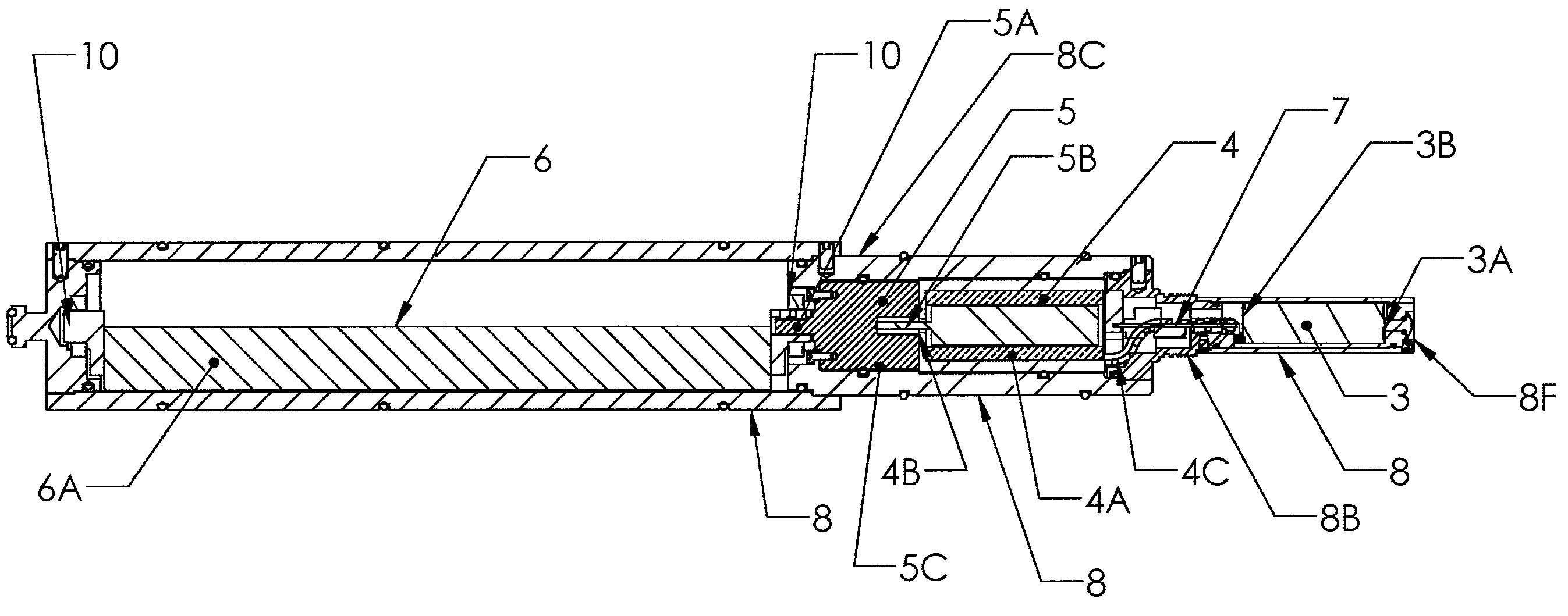
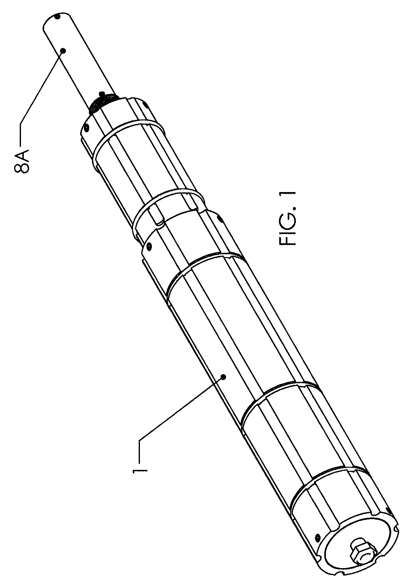
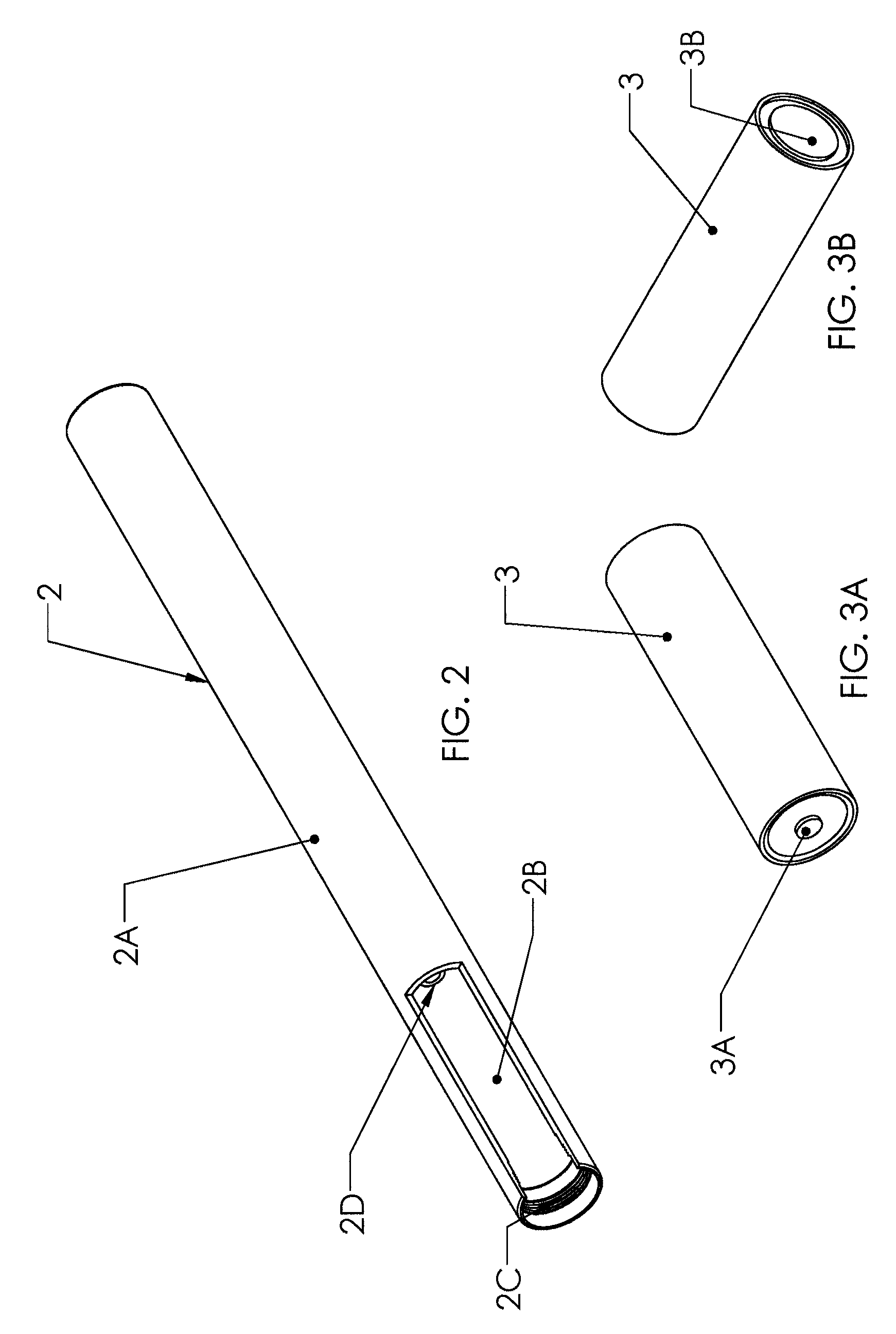
[0013]The present invention provides an electrical generating system for use in a horizontal directional drilling system. The drilling system has a generally horizontal drill stem that rotates. The electrical generating system comprises a generator and an eccentric mass. The generator has first and second components. The first component is coupled to rotate with the drill stem. The second component is capable of relative rotation with respect to the first component. One of the first and second components comprises an armature and the other of the first and second components comprises a field. The eccentric mass is mounted inside of the drill stem so as to rotate therein. As the drill stem rotates, the eccentric mass can remain stationary. The eccentric mass is coupled to the second component, wherein when the drill stem rotates, relative rotational motion is produced between the first and second components and the generator produces electrical power.

Problems solved by technology

The problem with this is that these batteries often fail during the drilling operation.
Pulling the drill stem out of the bore and replacing the batteries increases the cost of drilling.
Also, batteries need frequent changing requiring operator time to access the sonde.
Also once these batteries are “used up” they are thrown away, contributing to a more toxic environment.
This system is very time consuming and cannot be done on some drill rigs.
This system is relatively expensive to produce and is subject to break downs because of the corrosive nature of the drilling fluids.
These systems are relatively expensive.
Again this system is quite expensive.
This system is expensive and very unwieldy in a drill string.
This system does not produce an adequate amount of power.

Method used


Image

  • Counterbalance enabled power generator for horizontal directional drilling systems
  • Counterbalance enabled power generator for horizontal directional drilling systems
  • Counterbalance enabled power generator for horizontal directional drilling systems

Examples


Embodiment Construction

[0051]The present invention is used in a drill stem for Horizontal Directional Drilling (HDD). HDD is used to drill horizontal boreholes close to the earth's surface. Such boreholes extend, for example, under roads, buildings, and rivers, and are used to bury utilities, such as telephone and water lines.

[0052]The present invention utilizes generator components to generate electrical power downhole for the purpose of providing continuous power to a sonde in a drill stem. With the present invention a rechargeable power source (RPS) is charged and recharged whenever the drill string is rotated. The sonde draws electrical power from the rechargeable power source. Alternatively, the sonde could draw power, directly from the generator components with or without drawing power from the rechargeable power source, or from a combination of the generator components and a non-rechargeable power source.

[0053]The generator is driven by the rotation of the drill stem. The generator body or stator i...


PUM


Abstract

An electrical generating system is used for a horizontal directional drilling system. The drilling system has a generally horizontal drill stem that rotates. A generator has first and second components. The first component rotates with the drill stem, while the second component is able to rotate with respect to the first component. An eccentric mass is rotatably mounted inside of the drill stem and is coupled to the second component, wherein as the drill stem rotates, relative rotational motion is produced between the first and second components and the generator produces electrical power. The eccentric mass is mounted on two spaced apart mounting points inside of the drill stem. The generator provides power to a sonde. The generator is in a housing which has flow channels that allow drilling fluid to flow through the drill stem.

Description

[0001]This application claims the benefit of U.S. provisional application Ser. No. 60 / 988,952, filed Nov. 19, 2007.FIELD OF THE INVENTION[0002]The present invention relates to electrical generating systems for horizontal directional drilling systems.BACKGROUND OF THE INVENTION[0003]Horizontal directional drilling (HDD) operations are used in drilling for utilities such as water and telephone lines. In HDD, the boreholes are shallow and typically extend under roads, rivers and other obstacles. To drill the borehole, a drill string is equipped with a drill bit. The drill string is rotated and forced through the ground. Fluid in the form of water or drilling mud is circulated through the drill stem, out the drill bit and back to the surface on the outside of the drill stem.[0004]Drill stems or strings typically contain a sonde. The sonde is located near the drill bit and transmits a signal. One such sonde is shown and described in U.S. Pat. No. 5,155,442. An operator on the surface abo...

Claims


Application Information

Patent Timeline
Patent Type & Authority Patents(United States)
IPC IPC(8): E21B7/06
CPCE21B7/046E21B41/0085
Inventor WEBB, CHARLES T.
Owner WEBB CHARLES T
Learn More