
Corn stalk baling method and apparatus

a baling method and corn stalk technology, applied in baling, presses, agriculture tools and machines, etc., can solve the problems of large pile of corn stalks to be pushed along, inordinate wear of individual components of the baler, and inability to easily flow into the baler pickup

Active Publication Date: 2010-10-26
VERMEER MFG CO
View PDF32 Cites 29 Cited by
  • Summary
  • Abstract
  • Description
  • Claims
  • Application Information

AI Technical Summary

Problems solved by technology

It is this third category of crop material which is the most problematic to bale, primarily because of the stiff long pieces of plant stalk.
Because the corn stalks do not fold together like hay and straw material, sometimes the corn stalks do not flow easily into the baler pickup.
This causes the cornstalks to pile up in front of the pickup as the baler is towed through a field, causing a large pile of corn stalks to be pushed along in front of the baler pickup instead of evenly entering the baler.
This problem can occur numerous times during the process of baling a field of cornstalks.
Another problem with baling corn stalks is that the stiff stalks cause inordinate wear on individual components of the baler, especially on the pickup section of a baler as compared to using the baler for baling hay or straw.

Method used


Image

  • Corn stalk baling method and apparatus
  • Corn stalk baling method and apparatus
  • Corn stalk baling method and apparatus

Examples


embodiment 5

[0028]FIG. 9 shows another preferred embodiment 5 with a chopper type pickup 50 which can be like the chopper pickup of U.S. Pat. No. 3,732,672 to Adee et al., and U.S. Pat. No. 3,691,741 to White et al. This chopper / pickup 50 is a single stage pickup which not only picks up the crop 14 from the ground but chops it and throws or blows the crop upwardly through the chute 77 to the accumulator 73. The accumulator 73 has a bottom having conveyor belts 71 and 72 are operated to transfer the crop 14 to into the inlet 57 of the baler 58. Of course in this embodiment 5, it is contemplated that all of the features disclosed above with respect to embodiments 1 and 2 can be used as well if desired.

[0029]FIG. 10 shows the pickup portion only of a preferred embodiment 6. The pickup portion 80 has a front pickup 81 with teeth 82 all of which can be, for example, like U.S. Pat. No. 6,948,300 to Banstra et al., which is incorporated herein by reference in its entirety. A chopper / thrower / blower sec...

second embodiment

[0033]FIGS. 1-10 shows a baler 18 making approximately a six foot (6′) diameter bale, and FIGS. 11-13 shows a baler 118 making a ten foot (10′) diameter bale 118, which could also be 96 inches to 102 inches wide bale, for example. By using this second embodiment of the invention of FIGS. 11-13, a bale 128 can be made that is much larger in width than heretofore possible while still using other standard equipment such as mowers, mower conditioners and rakes that make conventional size windrows.


PUM


Abstract

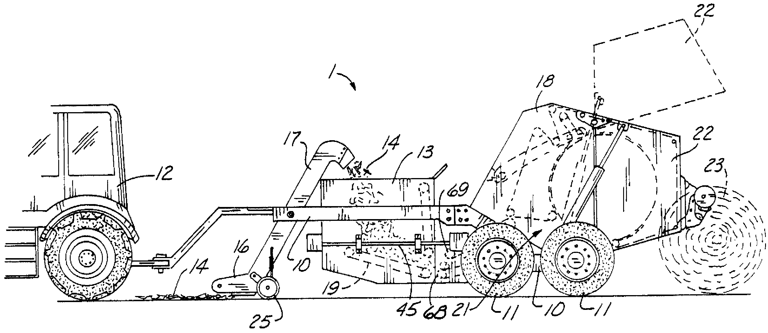
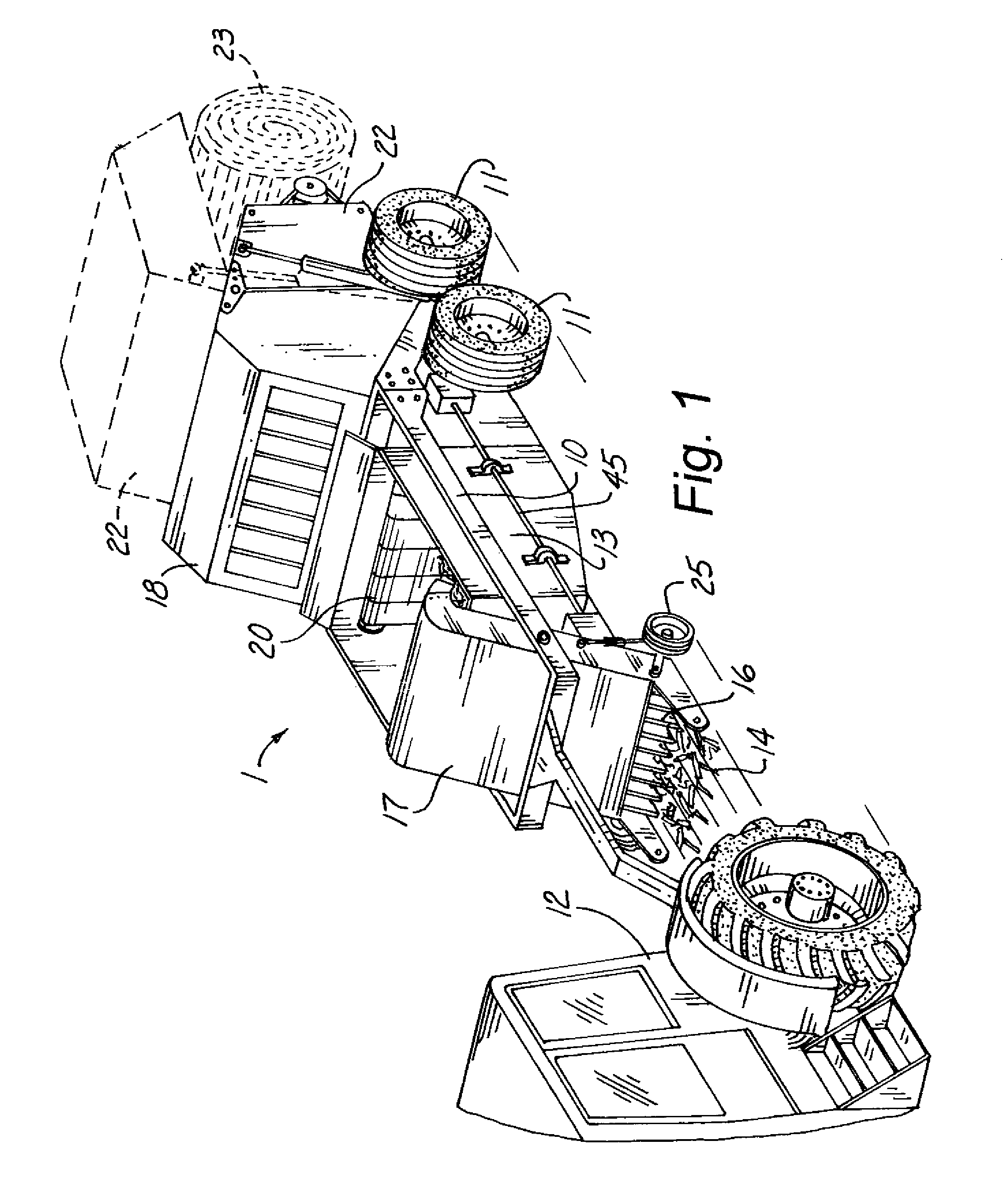
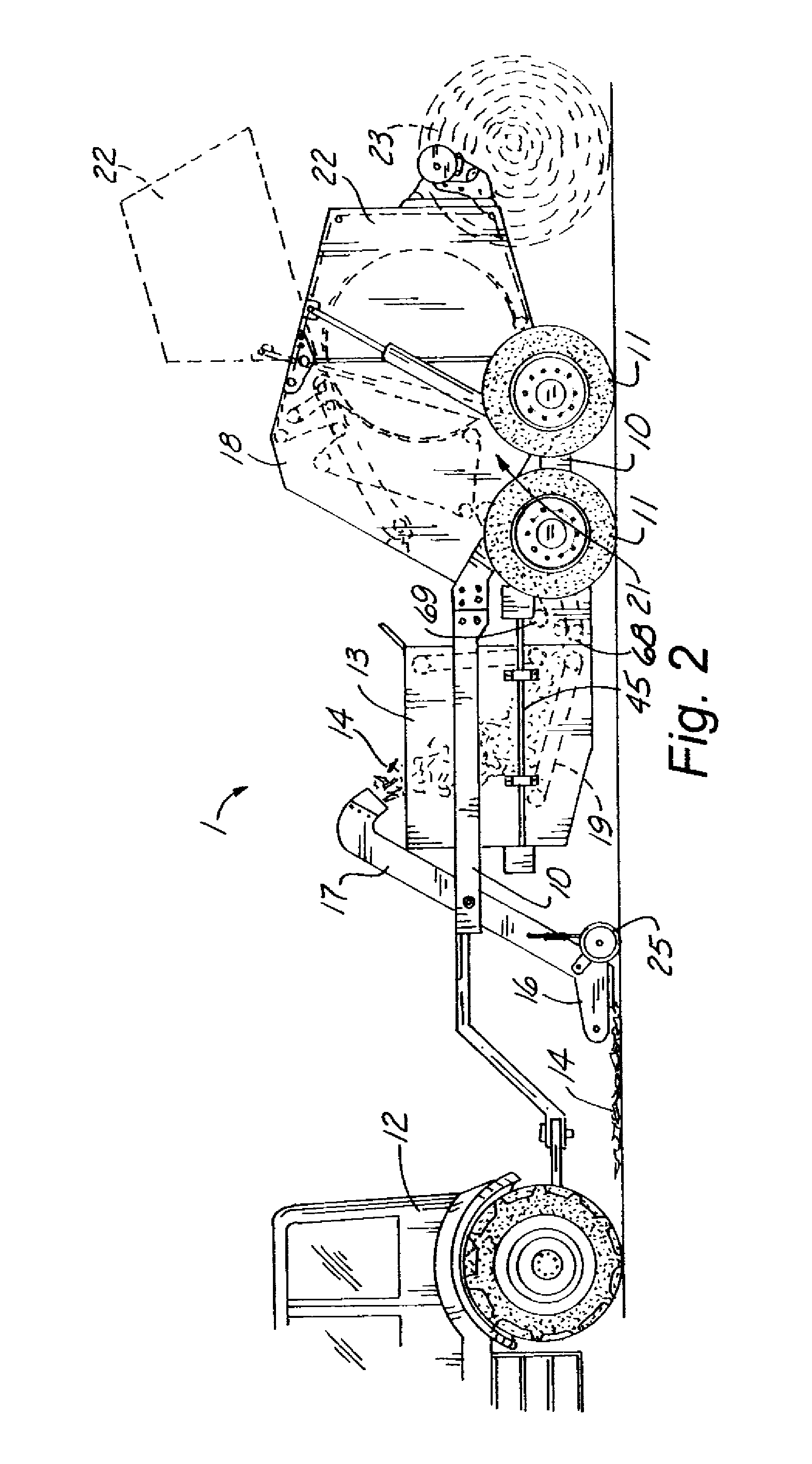
A method and apparatus for baling a crop with stiff stalks such as corn stalks has a frame with a front and a rear. At least one ground engaging wheel operatively attached to the frame for facilitating movement of the frame in a forward direction. An accumulator is operatively attached to the frame for holding the crop in various amounts. A pickup is operatively attached to the front of the frame for picking up the crop from a field and transferring the crop into the accumulator. A baler is operatively attached to the frame behind the accumulator for transforming a crop into a bale. A transfer mechanism such as a conveyor is provided in the accumulator for moving the crop in the accumulator to the inlet of the baler. In another embodiment, a pickup of a first predetermined width is provided for picking up the crop from a field and transferring the crop into the accumulator. The baler has an inlet and a baling chamber of a second predetermined width that is significantly larger than the first predetermined width of the pickup so that a larger bale can be made. The transfer mechanism can be in segments which are independently operable.

Description

FIELD OF THE INVENTION[0001]The present invention relates generally to agricultural equipment, and more specifically to a corn stalk baling method and apparatus.BACKGROUND OF THE INVENTION[0002]Balers are used for many different crops. Most balers are used to bale hay. Hay is usually classified as any type of grass or legume, such as alfalfa, that is fed to livestock such as cows and horses.[0003]Balers also bale straw, which is the part of the plant above ground that is left after grain such as wheat, oats barley or the like are harvested, for example with a combine harvester. A primary use for straw is for bedding for animals. Straw is also commonly used as mulch for gardens or the like.[0004]A third category of crop material which is baled using a baler is a stiff stalk crop, such as corn stalks, which are typically baled after the corn is removed from the stalk, such as with a combine harvester which saves only the corn kernels or with a corn picker, which saves only the corn wh...

Claims


Application Information

Patent Timeline
Patent Type & Authority Patents(United States)
IPC IPC(8): A01D39/00
CPCA01D89/003A01F15/106
Inventor REMPE, SCOTT A.DUNHAM, LISLE J.CORE, MARK D.
Owner VERMEER MFG CO
Learn More