Supercharge Your Innovation With Domain-Expert AI Agents!

Strain relief backshell assembly

a backshell and assembly technology, applied in the direction of electrical equipment, connection, coupling device connection, etc., can solve the problem of increasing assembly costs

Active Publication Date: 2010-11-23
AMPHENOL CORP
View PDF13 Cites 56 Cited by
  • Summary
  • Abstract
  • Description
  • Claims
  • Application Information

AI Technical Summary

Benefits of technology

Enables flexible configuration of cables with respect to electrical connectors, reducing costs and allowing for field adjustments without the need for multiple backshell assemblies, while maintaining effective EMI protection.

Problems solved by technology

That requires separate tooling for each configuration, thereby increasing costs of the assemblies.

Method used


Image

  • Strain relief backshell assembly
  • Strain relief backshell assembly
  • Strain relief backshell assembly

Examples


Embodiment Construction

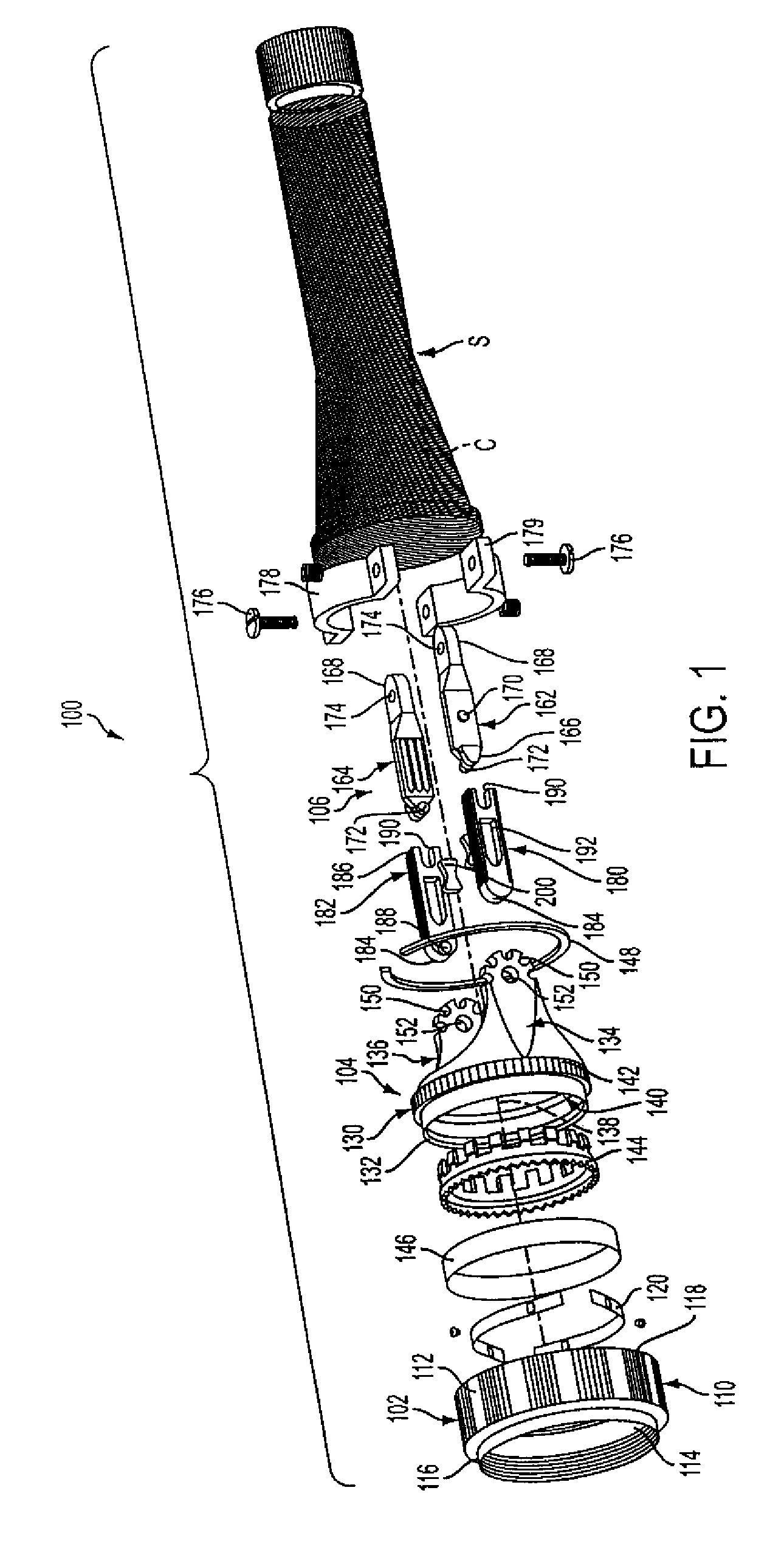
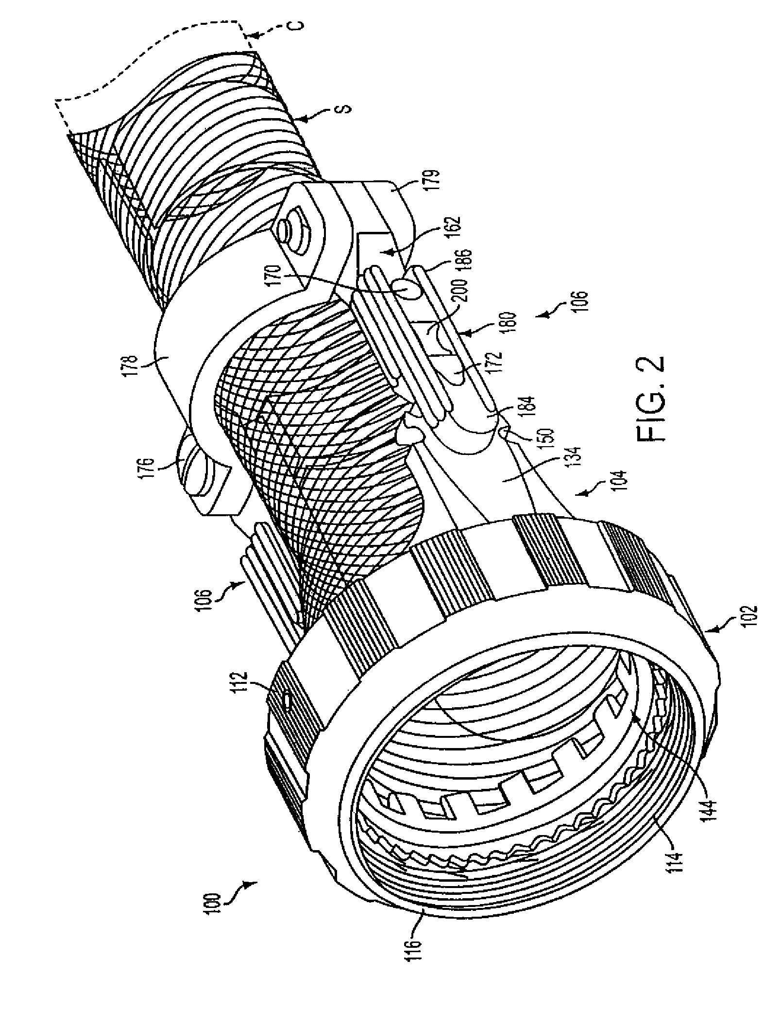
[0021]Referring to FIGS. 1-6, the present invention relates to a strain relief backshell assembly 100 for coupling an electrical connector 600 (FIG. 6) with EMI braid shield S covering a cable C. The backshell assembly 100 allows adjustment of the position of the cable C with respect to the connector without having to disassemble the components of the backshell assembly 100. The backshell assembly 100 is also configured to provide improved EMI protection.

[0022]In general the strain relief backshell assembly 100 includes a coupling nut 102 that interfaces with the electrical connector; a backshell housing 104 that receives and terminates the shielding braid of cable C and mates with the coupling nut 102; and an adjustable strain relief structure 106 that clamps to the cable C, couples to the backshell housing 104, and allows adjustment of the position of the cable C with respect to the backshell housing 104. The adjustable strain relief structure 106 allows in field adjustment of the...


PUM


Abstract

A backshell assembly that includes a housing configured to terminate a cable. The housing has a main body defining a central longitudinal axis, a connector interface for mating with an electrical connector, and at least one adjustment extension extending from the main body opposite the connector interface and substantially parallel to the central longitudinal axis. An adjustable strain relief structure is coupleable to the cable and the housing. The adjustable strain relief structure including at least one adjustment member cooperating with the adjustment extension of the housing such that the adjustment member is pivotable between different cable positions with respect to the central longitudinal axis of the housing. A movable locking member is coupleable with the adjustment extension of the housing and the adjustment member of the adjustable strain relief structure to releasably lock the adjustment member in a selected cable position with respect to the housing. A biasing member is supported by the locking member. The biasing member biasing the locking member into engagement with the adjustment extension of the housing and the adjustment member. The biasing member allows adjustment of the adjustment member between the different cable positions with respect to the adjustment extension of the housing without disassembly of the housing and the adjustable strain relief structure.

Description

FIELD OF THE INVENTION[0001]The present invention relates to a strain relief backshell assembly that terminates a cable for mating with an electrical connector. The strain relief backshell assembly is adjustable to different configurations of the cable with respect to the electrical connector.BACKGROUND OF THE INVENTION[0002]Backshell assemblies provide a transition between a cable and an electrical connector. Strain relief backshell assemblies in particular provide a clamping force on the wire bundle of the cable to prevent damage to the termination of the wires at the electrical connector. Various configurations of the backshell assemblies are known. For example, 0°, 45° and 90° configurations of backshell assemblies are known in which the configurations are defined by the angle between the cable and the backshell assembly. Conventional backshells are typically available in both EMI and Non-EMI versions. EMI backshells provide termination of cable shielding braid through a series ...

Claims


Application Information

Patent Timeline
Patent Type & Authority Patents(United States)
IPC IPC(8): H01R13/58
CPCH01R13/5804H01R13/5841H01R13/622
Inventor BALDWIN, BRENDON A.GALLUSSER, DAVID OTISPORCARO, BENARDINO F
Owner AMPHENOL CORP
Features
  • R&D
  • Intellectual Property
  • Life Sciences
  • Materials
  • Tech Scout
  • Unparalleled Data Quality
  • Higher Quality Content
  • 60% Fewer Hallucinations
Learn More