Suction cup having compact axial installation and release mechanism

a suction cup and axial release technology, applied in the field of suction cups, can solve the problems of limiting the degree of vacuum which can be achieved, the suction cup is difficult to properly position, and the attachment of the suction cup to an object can also be a problem

Active Publication Date: 2010-12-14
CARNEVALI JEFFREY D
View PDF36 Cites 88 Cited by
  • Summary
  • Abstract
  • Description
  • Claims
  • Application Information

AI Technical Summary

Problems solved by technology

Suction cups are difficult to properly position.
Attachment of the suction cup to an object can also be a problem.
The result is a limit on the degree of vacuum which can be achieved.
One problem with arrangements using crankshafts and eccentric rods is the lever arms which extend out from whatever device they are mounted in.
The lever arms is all too easy to hit or snagged, and the suction is thereby accidentally released.
Another drawback of lever arms is that the support and bearing structure for them is difficult to integrate into the structure of the device which is utilizing the suction cups.
This complication increases costs and the likelihood of failure.
A further cause of increased costs associated with such suction cup assemblies according to the prior art is that they usually require suction cups that must be specially designed to accommodate the lever arms, crankshafts, and the like.
The axial suction cup devices of Holoff, et al. and Belokin, et al. and others however are overly complex to manufacture, assemble and operate, as well as suffering other limitations.

Method used


Image

  • Suction cup having compact axial installation and release mechanism
  • Suction cup having compact axial installation and release mechanism
  • Suction cup having compact axial installation and release mechanism

Examples


Embodiment Construction

[0037]In the Figures, like numerals indicate like elements.

[0038]The terms “up” and “down” and derivatives are used solely for clarity in describing the invention and relate to the relative orientation of the individual components shown in the Figures and the assembly relative to a surface to which it is attached.

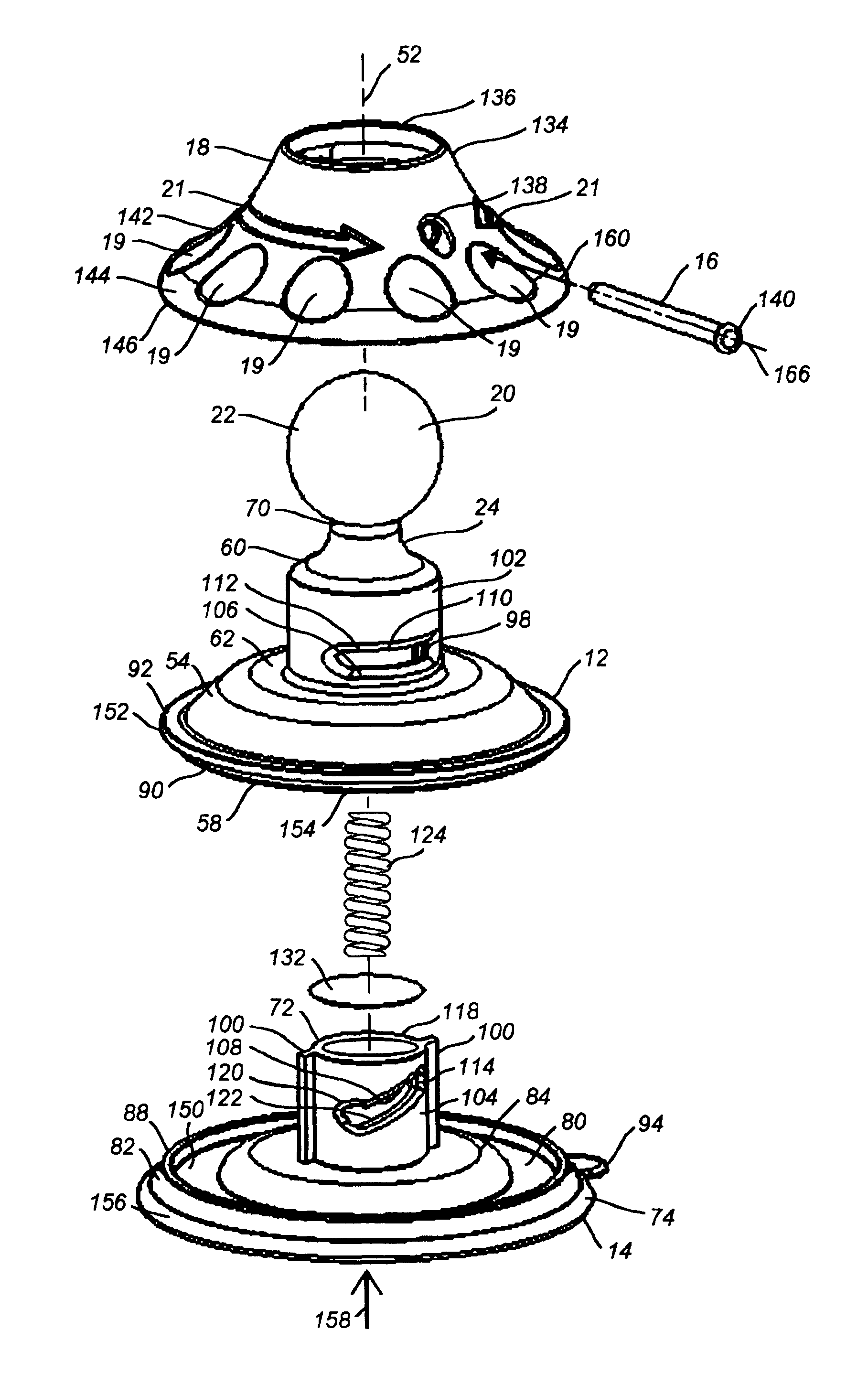
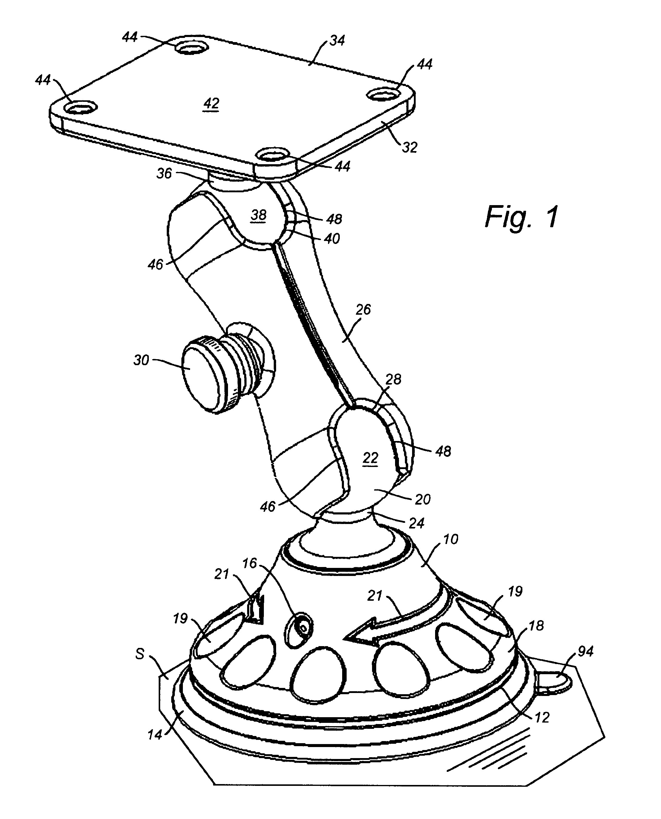
[0039]FIG. 1 is a pictorial view of the present invention embodied by example and without limitation as a suction cup device 10 having a novel compact axially-driven suction cup installation and release mechanism. Accordingly, as shown more clearly in subsequent Figures, a substantially “bell” shaped drive base 12 and a suction cup plunger assembly 14 are coupled to each other with a rigid drive pin 16. The drive pin 16 also couples the drive base 12 and suction cup plunger assembly 14 to an optional rotational drive member or “handle”18, which optionally includes one or both of a manual operating means 19 and one or more directional indicators 21.

[0040]The suction cup devi...


PUM


Abstract

A novel suction cup mounting apparatus having a novel compact axial suction cup installation and release mechanism and method for assembling such a suction cup apparatus. The suction cup device includes a suction cup portion of a plunger assembly fit within a concave drive base and coupled thereto by a rigid drive pin. An optional rotational drive member or “handle” structured to operate on an external surface of the drive base may be provided for manipulating the drive pin relative to the suction cup and drive base. The suction cup device is intended to secure some device—a “utilization device”—to a surface. Therefore, according to another aspect of the suction cup device, a utilization mounting surface is projected above the drive base.

Description

FIELD OF THE INVENTION[0001]The present invention relates to the field of suction cups, and in particular to axial suction cup installation and release devices and methods.BACKGROUND OF THE INVENTION[0002]Suction cups are generally well-known and commonly used to mount and secure objects to smooth surfaces such as the surfaces of glass, plastic, Formica, glazed tile, metal, and other smooth surfaces. A typical suction cup includes a cup body and a stem. The cup body is generally arcuate or circular and defines a concavity. Typically, the stem is integrally formed on the body and used as the place of attachment for the object to be supported by the suction cup. At least the body of the suction cup is made of rubber, plastic or other material having sufficiently elastically resilient properties such that, when the body is pressed against a smooth surface, the volume of concavity is reduced, thereby forcing air to be expelled so that the body forms an air-tight seal against the smooth ...

Claims


Application Information

Patent Timeline
Patent Type & Authority Patents(United States)
IPC IPC(8): A45D42/14F16B47/00
CPCF16B47/00
Inventor CARNEVALI, JEFFREY D.
Owner CARNEVALI JEFFREY D
Why Eureka
Try Eureka