Luminaire reflector with light-modifying flange

a technology of reflector and flange, which is applied in the field of luminaires, can solve the problems of unwanted annulus light entering the reflector wall through the inner surface, and the inner and outer walls are trapped, so as to reduce the brightness of light passing through the flange, less noticeable, less objectionable or even decorative

Active Publication Date: 2010-12-14
ABL IP HLDG
View PDF9 Cites 7 Cited by
  • Summary
  • Abstract
  • Description
  • Claims
  • Application Information

AI Technical Summary

Benefits of technology

[0008]In accordance with the invention, the flange is configured to direct trapped light incident on a flange into desired directions or patterns. In one embodiment, the bottom face of the flange is beveled whereby the beveled part refracts the incident trapped light over a range of angles that moves it away from the nadir (i.e., raises it) and also spreads it out. This reduces the brightness of the light passing through the flange and makes it less noticeable. The beveled face may be planar or curved (e.g., an arc, ellipse, or parabola) or formed by a plurality of smaller line segments or by lenticular elements. As well, the flange may be provided with multiple prisms.
[0010]It is an object of this invention to provide structure that modifies light trapped in a luminaire wall and incident on a flange of the luminaire by changing its color, intensity, or direction to result in a desired light pattern.

Problems solved by technology

A problem with the prior reflectors of this type is that the some of the light entering the reflector wall through the inner surface becomes trapped between the inner and outer walls.
In the general case, this annulus of light passing through the flange is unwanted.

Method used


Image

  • Luminaire reflector with light-modifying flange
  • Luminaire reflector with light-modifying flange
  • Luminaire reflector with light-modifying flange

Examples


Embodiment Construction

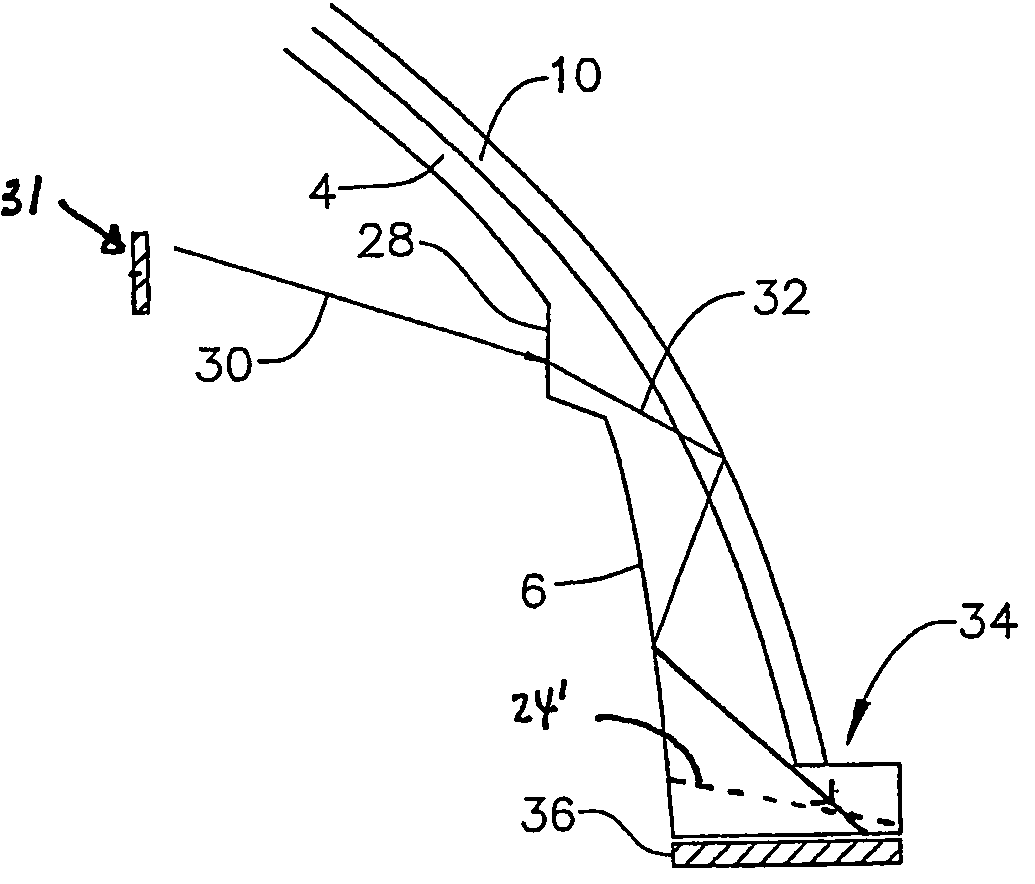
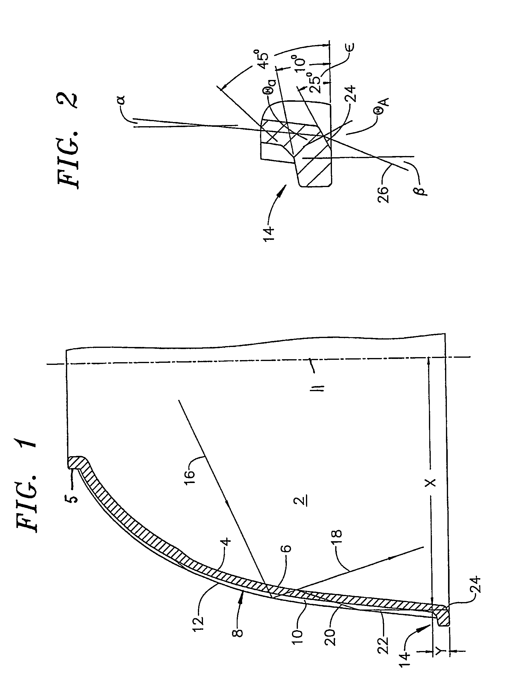
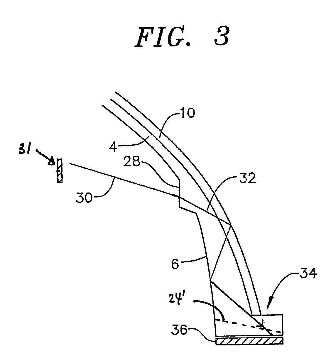
[0014]With reference to the drawing figures, FIG. 1 is a partial vertical cross section of a luminaire reflector 2 formed by a wall 4 of generally transparent material, such as glass or acrylic plastic. The reflector is configured to reflect light originating from a source (not shown) that is centrally located in the reflector as is known in the art. The inner surface 6 of the wall 4 is generally smoothly curved but may be provided with a more complex shape as is known in the art.

[0015]The reflector wall 4 is made reflective by providing a series of prisms 8 on the outer surface of the wall 4. The prisms are formed by faces 10 that extend longitudinally along the wall in a prescribed curve to form the outer surface of the wall. Adjacent pairs of faces 10 form a dihedral angle of 90° and intersect at peaks 12. By this arrangement, light rays from the light source entering the wall from the central portion of the reflector are generally reflected by the prism faces 10 by total interna...


PUM


Abstract

A luminaire reflector of the type that is dome-shaped and includes a flange at the bottom provides a modified a flange that alters the pattern or other effect of light trapped in the wall of the reflector and exiting through the flange. When the bottom surface of the flange is angled with respect to the horizontal, the light exiting the flange is spread and lifted. In accordance with another embodiment, the flange is provided with a colored layer to provide decorative effects to the light exiting the flange.

Description

[0001]This application is the national stage of International Application Number PCT / US2005 / 043676, filed Dec. 2, 2005, which was published in English, and claims priority of U.S. Provisional Application No. 60 / 632,665, filed Dec. 3, 2004.TECHNICAL FIELD[0002]This invention relates to the art of luminaires. In particular, the invention relates to a luminaire with a reflector having a plurality of prismatic reflectors that reflect incident light from a source onto an area to be illuminated.BACKGROUND ART[0003]Luminaires are known that comprise a series of generally vertical, right-angle prisms for reflecting light from a centrally located lamp. The reflectors for these luminaries are made with transparent material (glass, acrylic, etc.) and typically have sets of longitudinal prisms running from top to bottom. The reflector typically has a desired overall contour provided by the series of prisms. In most cases the desired overall contour is dome-like, with an upper part of smaller di...

Claims


Application Information

Patent Timeline
Patent Type & Authority Patents(United States)
IPC IPC(8): F21V9/00F21V7/22
CPCF21V5/02F21V7/0091F21V13/04
Inventor ABDELSAMED, YASER S.
Owner ABL IP HLDG
Why Eureka
Try Eureka