3D (three dimensional) display device and phase delay piece thereof

A phase delay film and phase delay technology, applied in the field of 3D imaging, can solve problems such as image crosstalk

Inactive Publication Date: 2012-08-15
TCL CHINA STAR OPTOELECTRONICS TECH CO LTD
View PDF4 Cites 4 Cited by
  • Summary
  • Abstract
  • Description
  • Claims
  • Application Information

AI Technical Summary

Problems solved by technology

When an attachment error occurs, the phase delay area corresponding to the alignment of one eye will move to the pixel area of ​​the other eye, and the viewer's eyes may see the input image of the other eye, causing image crosstalk

Method used


Image

  • 3D (three dimensional) display device and phase delay piece thereof
  • 3D (three dimensional) display device and phase delay piece thereof
  • 3D (three dimensional) display device and phase delay piece thereof

Examples


Embodiment Construction

[0033] In order to make the above objects, features and advantages of the present invention more comprehensible, preferred embodiments of the present invention are exemplified below and described in detail in conjunction with the accompanying drawings. Furthermore, the directional terms mentioned in the present invention, such as "up", "down", "front", "back", "left", "right", "inside", "outside", "side", etc., It is only for orientation with reference to the attached drawings. Therefore, the directional terms used are used to illustrate and understand the present invention, but not to limit the present invention.

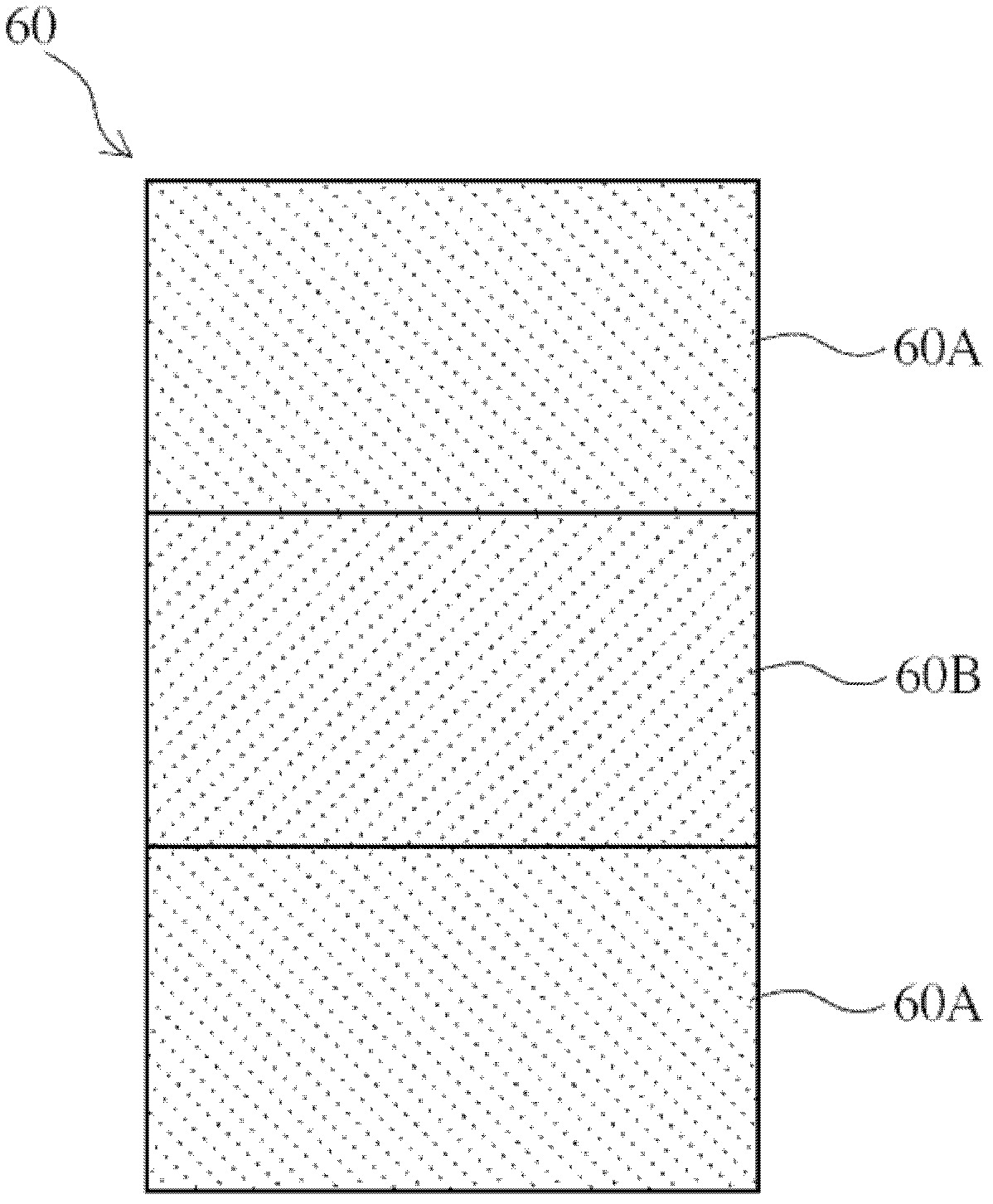
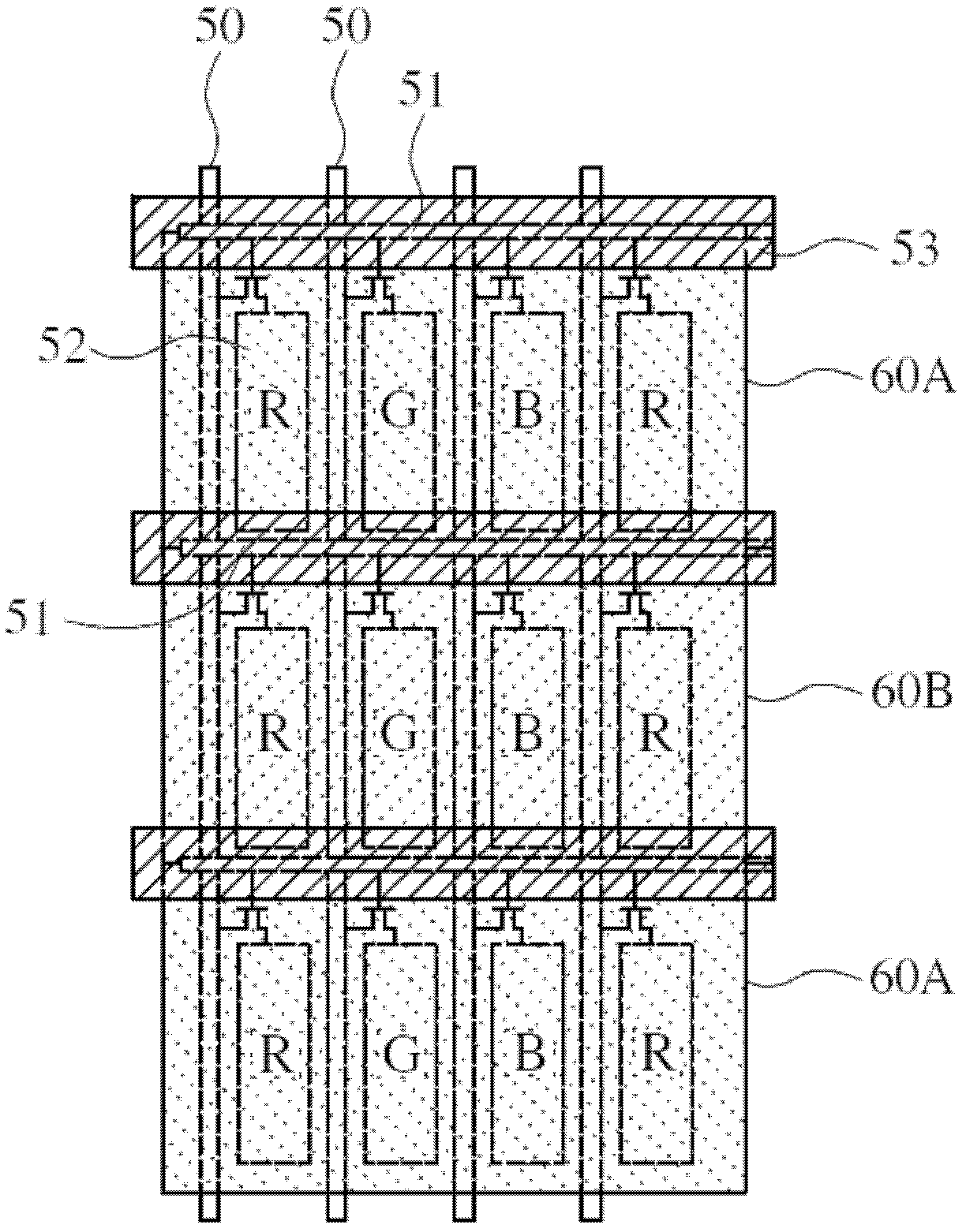
[0034] Please refer to Figure 4 as shown, Figure 4 It is a partial schematic diagram of a preferred embodiment of the phase retarder of the present invention. The phase retarder of the present invention is applied in a 3D display device. The 3D display device mainly includes a liquid crystal display panel and the phase retarder 10 .

[0035] Generally speaki...


PUM


Abstract

The invention discloses a 3D (three dimensional) display device and a phase delay piece of the 3D display device. The phase delay piece is arranged on an external surface of a polaroid and comprises multiple first phase delay unit lines, multiple second phase delay unit lines and non-phase delay unit lines, wherein the second-phase delay unit lines and the first phase delay unit lines are arranged in a staggering manner, each non-phase delay unit line is arranged between the adjacent first phase delay unit lines and second phase delay unit line; an optical axis of the non-phase delay unit lines are vertical or parallel to a penetrating shaft of the polaroid; and according to the non-phase delay unit lines, the brightness of juncture of a phase delay region can be weakened, and further improve image interference caused by the attaching and the shifting of the phase delay piece can be improved.

Description

【Technical field】 [0001] The invention relates to 3D display technology, in particular to a 3D display device and a phase retarder. 【Background technique】 [0002] Because people's eyes have a certain distance between them, the directions of objects seen by both eyes are not exactly the same. Therefore, the 3D display utilizes the parallax of the two eyes of human beings to provide different images to the two eyes respectively to produce a three-dimensional effect. [0003] refer to figure 1 As shown, an existing 3D imaging system is provided with a phase retardation layer consisting of a patterned half phase retardation layer 90 and a quarter wavelength phase retardation layer 91 on the light exit surface of a liquid crystal display panel. The retarder is used to deliver images with different polarization directions to the viewer. At the same time, the viewer wears polarized glasses 7, so that the left eye receives the image of a single polarization direction, while the r...

Claims


Application Information

Patent Timeline
IPC IPC(8): G02B5/30G02B27/26G02F1/13363G02B30/25
CPCG02B5/3083G02B30/25G02F1/13363G02F2413/04G02F2413/07
Inventor 萧嘉强陈峙彣
Owner TCL CHINA STAR OPTOELECTRONICS TECH CO LTD
Why Eureka
Try Eureka