

Charger
a technology of charging device and charging head, which is applied in the field of charging device, can solve the problems of power waste of the notification unit, and achieve the effects of reducing brightness, reducing the power consumption of the notification unit, and facilitating the change of operation sta
- Summary
- Abstract
- Description
- Claims
- Application Information
AI Technical Summary
Benefits of technology
Problems solved by technology
Method used
Image

Examples
first embodiment
[0041]In the first embodiment, the controller 2 may serve as the brightness reducing unit 15 for reducing the light brightness of the notification unit 3 as described above. Hereinafter, such a notification given by reducing the light brightness of the notification unit 3 is referred to as “brightness reducing notification,” and a notification given by an original brightness level before brightness reduction will be referred to as “original brightness notification.”
[0042]If the operation state of the charger 1 is changed during the brightness reducing notification, the controller 2 gives the original brightness notification by recovering the reduced brightness to the original brightness level.
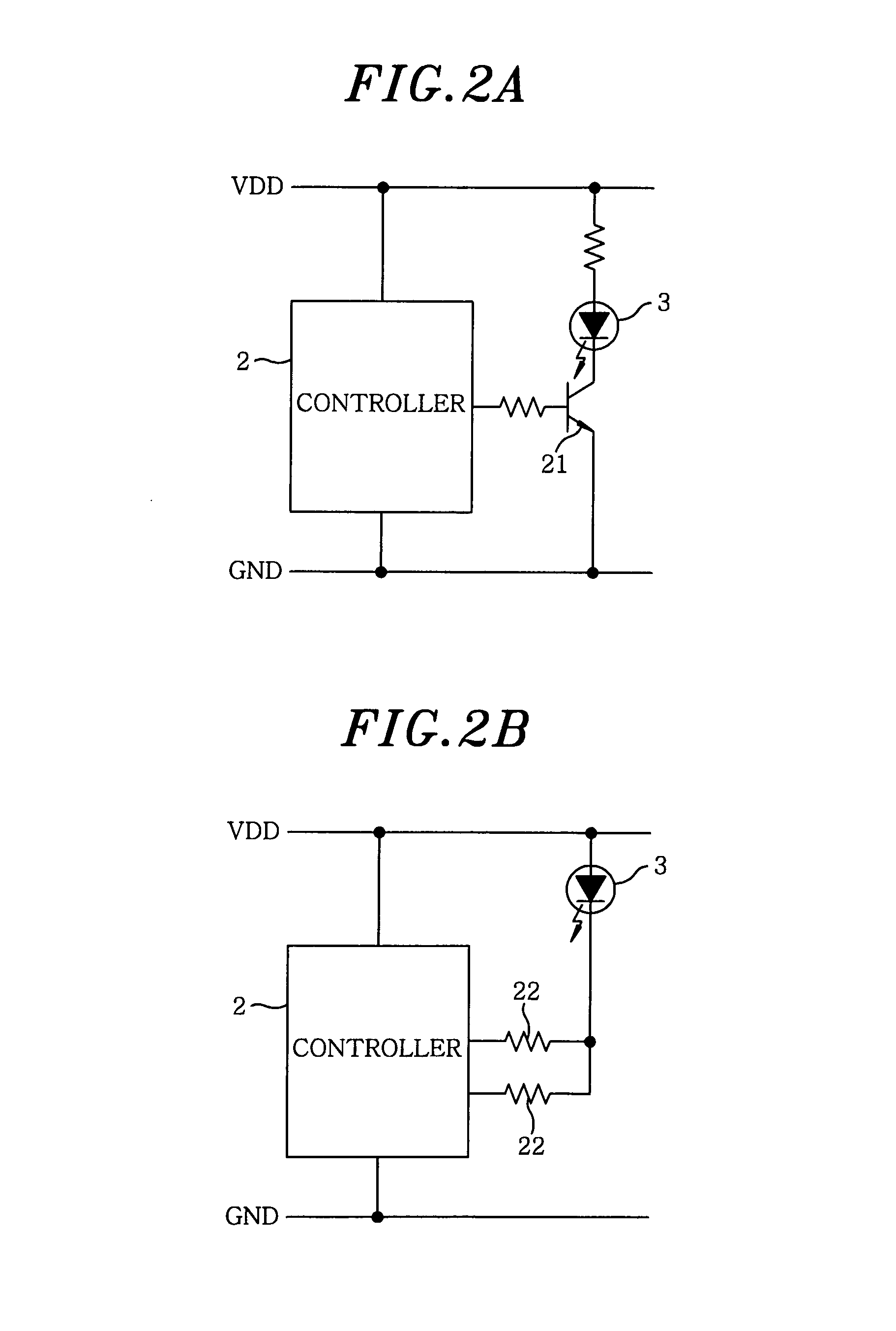
[0043]For instance, the notification unit 3 is connected to the collector of an n-p-n transistor 21 serving as the brightness reducing unit 3 and the base of the transistor 21 is connected to the controller 2 as shown in FIG. 2A. The controller 2 controls an H / L output to the base to turn on or...
second embodiment
[0083]In the second embodiment, the charger 1 includes the brightness reducing time changing unit 4 as described above; and the predetermined time T for reducing the light brightness of the notification unit 3 can be changed by externally manipulating a dial type manipulation unit 41 of the brightness reducing time changing unit 4.
[0084]For example, if a manipulation level is set to be “5” by manipulating the manipulation unit 41 as shown in FIG. 5B and if 5 minutes has elapsed during, e.g., the power connection state 101 or the charging state 103 without change, the controller 2 recognizes that the predetermined time T corresponding to the settings has elapsed and changes an original brightness notification to the brightness reducing notification 106.
[0085]Further, if the manipulation level is set to be “0” for example, the brightness reducing notification 106 is not to be given and the controller 2 does not reduce the light brightness of the notification unit 3.
[0086]In other word...
third embodiment
[0089]In the third embodiment, the charger 1 includes the brightness adjusting unit 7 as described above; and the light brightness of the notification unit 3 can be adjusted by externally manipulating a slide type manipulation unit 71 of the brightness adjusting unit 7.
[0090]For example, if the manipulation unit 71 is set to slide to a level closer to a minimum level (MIN), the light brightness of the notification unit 3 during the brightness reducing notification 106 gets darker than that before changing the setting. Further, if the manipulation unit is set to slide to MIN, the notification unit 3 is turned off when the brightness reducing notification 106 is given.
[0091]On the other hand, if the manipulation unit is set to slide to a level closer to a maximum level (MAX), the light brightness of the notification unit 3 during the brightness reducing notification 106 gets brighter than that before changing the setting. Further, if the manipulation unit is set to slide to MAX, the l...
PUM
 Abstract
Description
Claims
Application Information