Check patentability & draft patents in minutes with Patsnap Eureka AI!

Sliding mechanism with spring positioning

a technology of positioning mechanism and sliding device, which is applied in the direction of static indicating device, roof, instruments, etc., can solve the problems of requiring shielding, affecting the electronic performance of the device, and unsatisfactory for users to be required to hold the devi

Inactive Publication Date: 2010-12-14
INTERPLEX IND
View PDF4 Cites 6 Cited by
  • Summary
  • Abstract
  • Description
  • Claims
  • Application Information

AI Technical Summary

Problems solved by technology

It is undesirable for the user to be required to hold the device in the open position while using both the first and second surface.
Accordingly, most sliding devices have a locking mechanism that holds the sliding device in one of the open position and the closed position, but is weak enough that the user can easily change the position of the device by applying a slight pressure.
This mechanism is effective, but can interfere with the electronics of the device and thus, requires shielding.
Another drawback of these locking mechanisms is that they all require the user to operate the sliding device until it has locked in one of the open or closed positions.
If the user slides the members almost all the way to the locked position, but does not lock the device, there is a risk that the device will slide back to the previous position.

Method used


Image

  • Sliding mechanism with spring positioning
  • Sliding mechanism with spring positioning
  • Sliding mechanism with spring positioning

Examples


Embodiment Construction

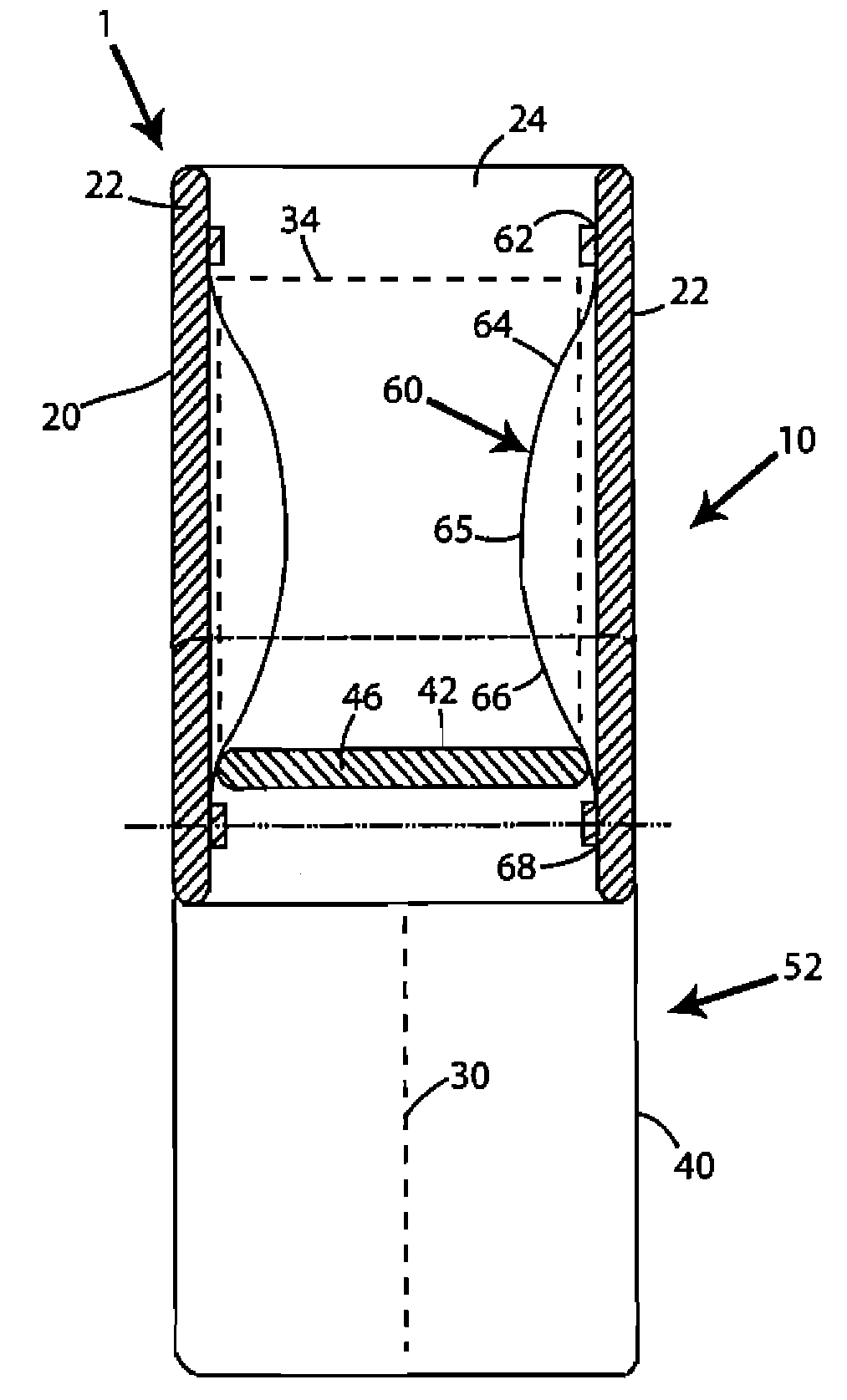
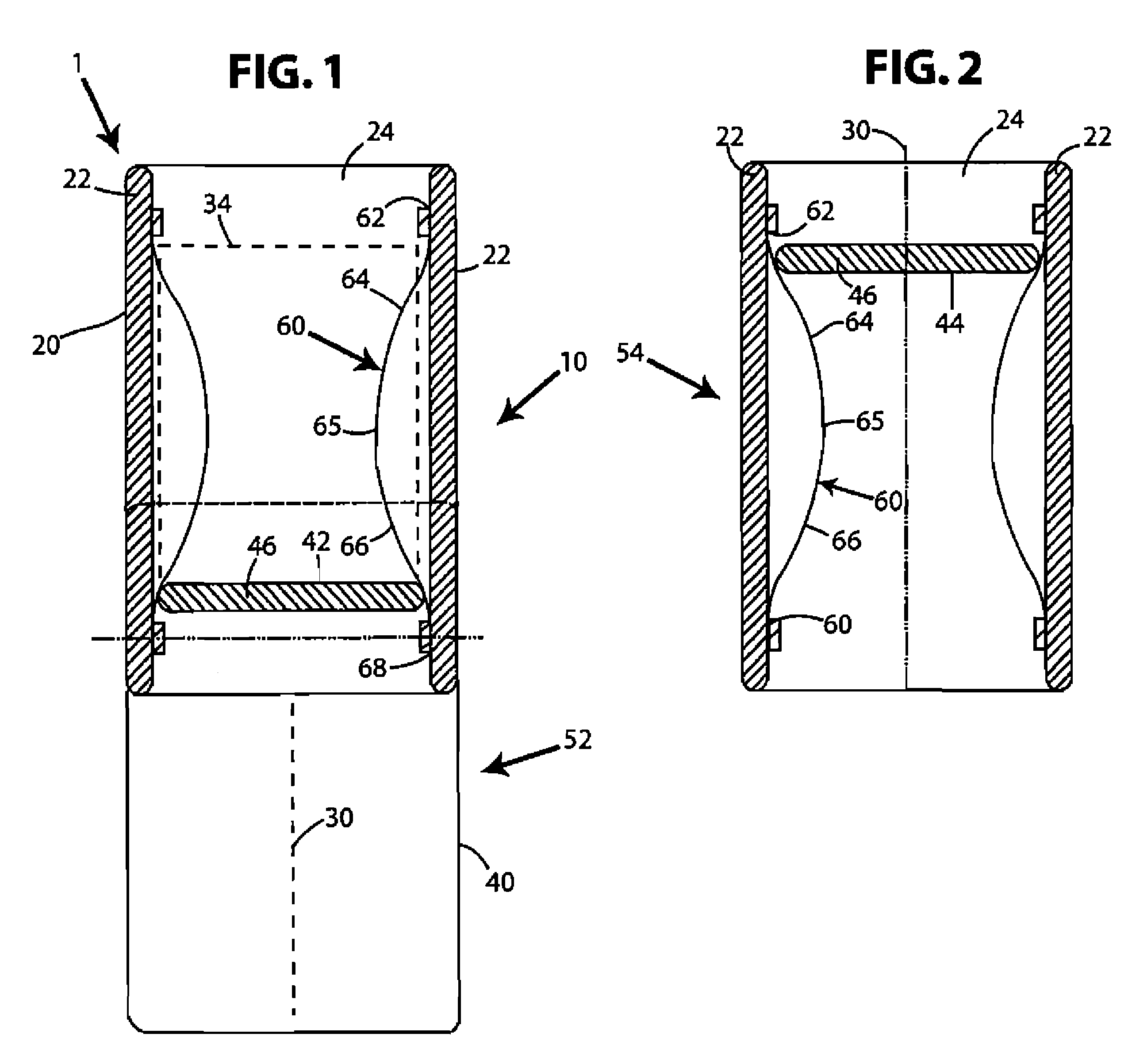
[0021]One embodiment of the sliding position mechanism according to the present invention is shown in FIGS. 1 and 2. The sliding position mechanism 10 is part of sliding device 1 which includes a top member 20 and a bottom member 40. The top member 20 and bottom member 40 are slidably attached and may slide along a sliding axis 30. In the description provided, the top member 20 is described as stationary and only the bottom member 40 slides. However, it is to be understood that the bottom member 40 may be held stationary and the top member 20 moved. The sliding device has two rest positions. In the illustrated embodiment, the rest positions are shown as an open position 52, as shown in FIG. 1, and a closed position 54, as shown in FIG. 2. In the open rest position 52 shown in FIG. 1, the top member 20 is displaced from bottom member 40 and only a section of bottom member 40 is obscured. In contrast, in the closed rest position 54 shown in FIG. 2, the top member 20 overlaps with the ...


PUM


Abstract

A sliding mechanism includes two members, one of which is slidable with respect to the other along an axis. One of the members slides back and forth with respect to the other between a first position and a second position. A leaf spring is used as a positioning element to hold one of the members in either the first position or the second position. The leaf spring is attached to one of the two members and the other of the two members includes a projection. The leaf spring abuts the projection holding the slidable member in either the first position or the second position. When a user pushes one of the members from one position to another, the projection pushes the leaf spring out of the way until it passes an apex of the leaf spring and is held in the other position.

Description

CROSS-REFERENCE TO RELATED APPLICATIONS[0001]The benefit of priority to U.S. Provisional Patent Application No. 60 / 801,647 filed on May 18, 2006 is claimed.STATEMENT REGARDING FEDERALLY SPONSORED RESEARCH[0002]Not ApplicableTHE NAMES OF THE PARTIES OF A JOINT RESEARCH AGREEMENT[0003]Not ApplicableINCORPORATION-BY-REFERENCE OF MATERIAL SUBMITTED ON A COMPACT DISC[0004]Not ApplicableBACKGROUND OF THE INVENTION[0005]1. Field of the Invention[0006]The invention relates to positioning mechanisms for sliding devices and, more specifically, relates to positioning mechanisms using a spring.[0007]2. Description of Related Art[0008]The use of devices which have two connected parts that slide relative to one another has become increasingly popular in the portable electronics industry. Typically, a top member slides over a bottom member in moving between an open position and a closed position. In the closed position a first surface on the front of the top member is viewable but a second surface...

Claims


Application Information

Patent Timeline
Patent Type & Authority Patents(United States)
IPC IPC(8): H04M1/00
CPCG06F1/1624G06F1/1677G06F1/1679H04M1/0237
Inventor SEIDLER, JACK
Owner INTERPLEX IND
Features
  • R&D
  • Intellectual Property
  • Life Sciences
  • Materials
  • Tech Scout
  • Unparalleled Data Quality
  • Higher Quality Content
  • 60% Fewer Hallucinations
Learn More