Lighted subway signage

a technology of subway tunnels and signs, applied in the field ofgraphic displays, can solve the problems of high cost, inconvenient installation, and inability to fix the screen in the subway tunnel, and achieve the effect of improving the visual effect, reducing the cost of installation, and improving the effect of visual

Inactive Publication Date: 2011-01-18
HINES STEPHEN P
View PDF8 Cites 32 Cited by
  • Summary
  • Abstract
  • Description
  • Claims
  • Application Information

AI Technical Summary

Benefits of technology

[0014]Accordingly, it is a primary object of the present invention to provide improved back-lighted images for viewers moving rapidly past such back-lighted images that rely upon a single vertical light source to provide multiple reflected line scans of transparent images located between the light source reflections and viewers.

Problems solved by technology

Locating signage in such tunnels will not generate the same types of concerns that often arise in connection with billboards and other signage in open, public places, which often is subject to regulation.
However, there are some difficulties with such signage, such as access for changing the signs and lamps, size and the need to catch the attention of riders, especially when they are passing through a tunnel at a relatively high rate of speed.
However, unlike motion pictures, the screen in a subway tunnel is not fixed.
One of the problems with such systems was high cost, and U.S. Pat. No. 4,393,742, issued in 1983, sought to reduce such cost by using a sensor to measure the velocity of a train and then initiate the flash cycle based upon the results of the sensor.
Another problem with such systems was the triggering mechanism for illuminating the series of displays, and one invention directed to this problem is U.S. Pat. No. 5,108,171, issued in 1992.

Method used


Image

  • Lighted subway signage
  • Lighted subway signage
  • Lighted subway signage

Examples


Embodiment Construction

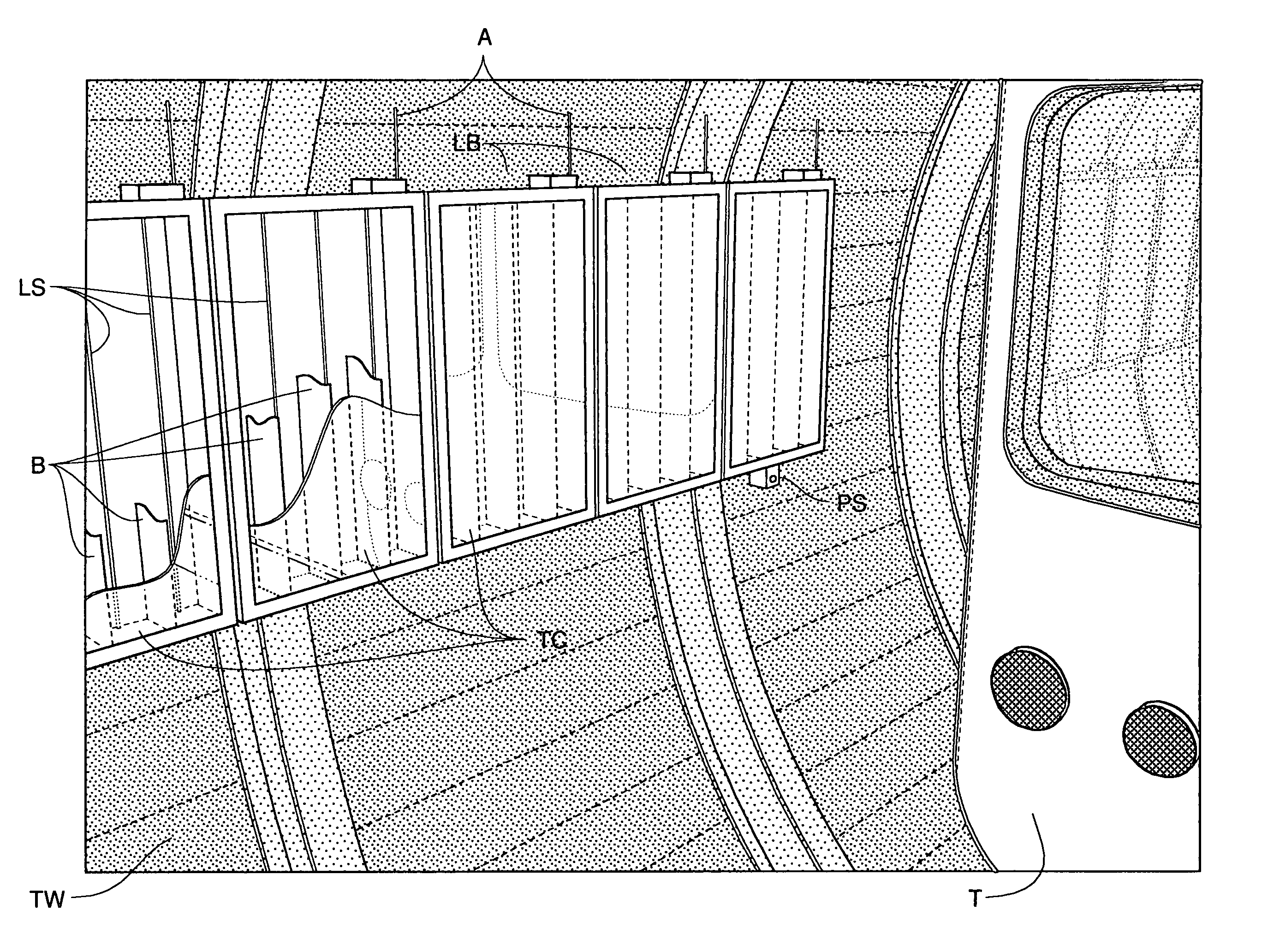
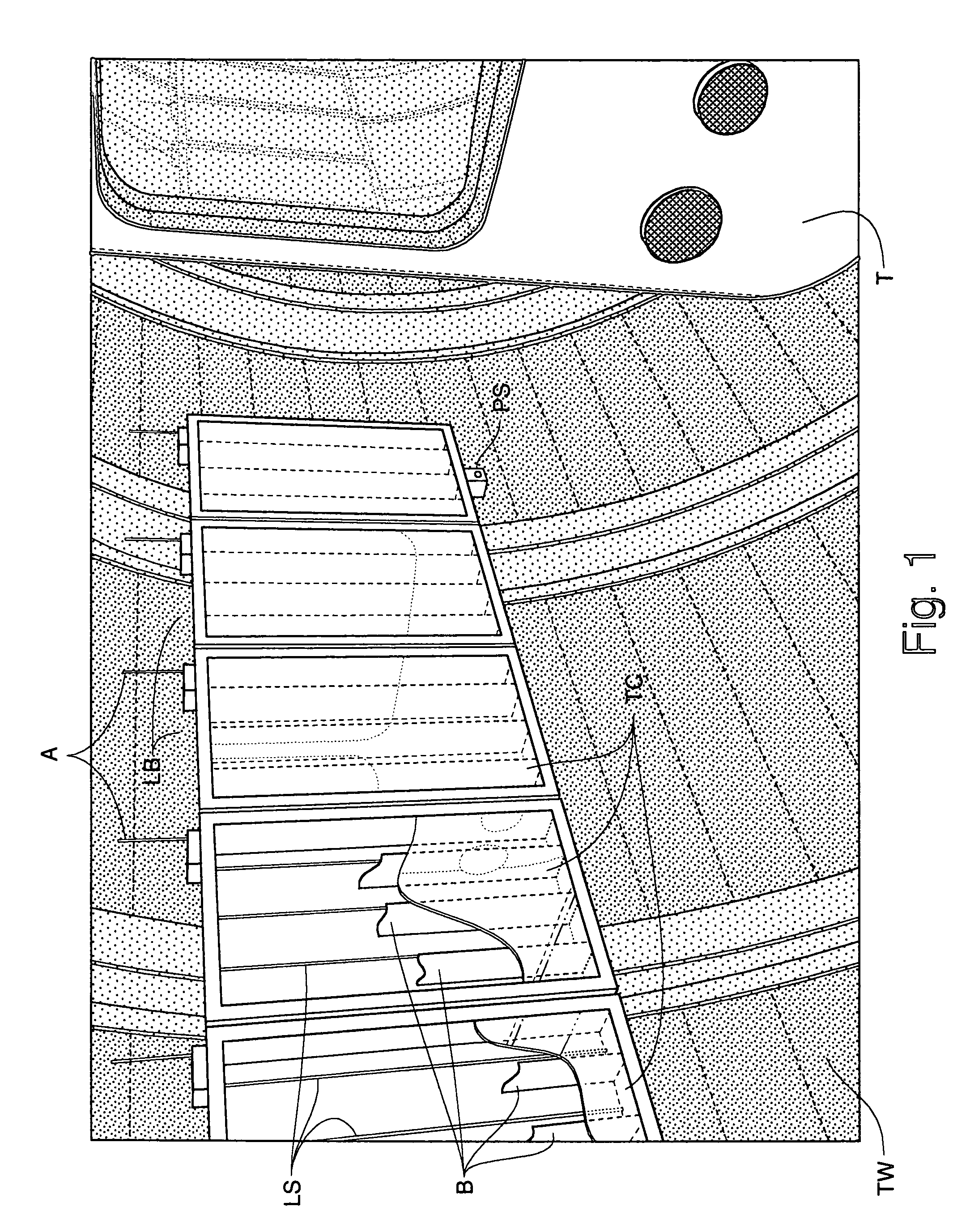
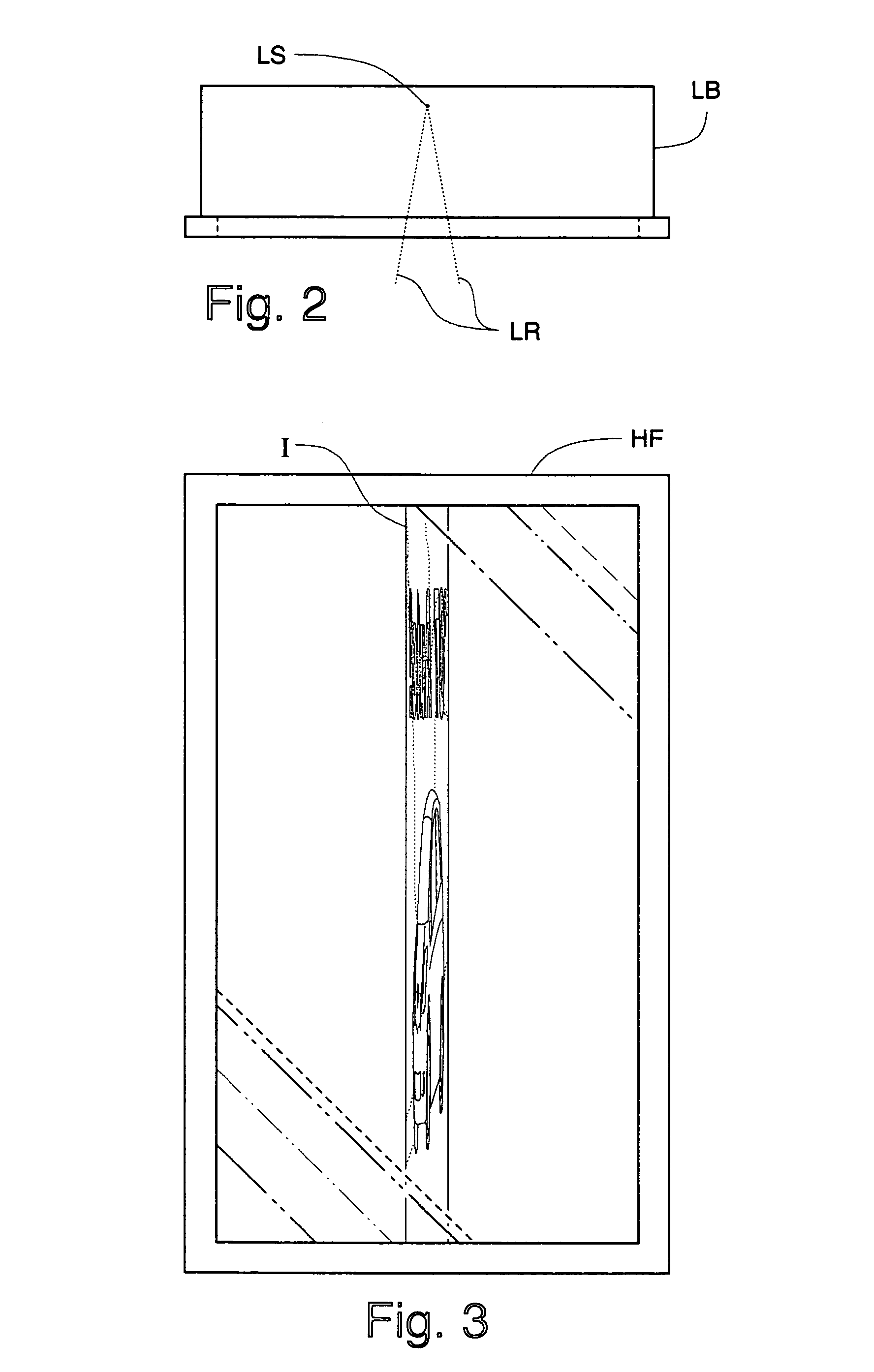
[0053]As this is a continuation-in-part application which is an improvement over the inventions that I disclosed in my earlier applications, I will first describe the original invention and my first improvements thereto for context, and then describe my present invention. However, to aid the reader in understanding my disclosures, the following is a glossary of the elements identified in the Figures:[0054]∝ Vertical Viewing Angle, FIG. 34[0055]A Antenna, FIG. 1[0056]β Horizontal Viewing or Illumination angle, FIG. 35[0057]B Baffle, FIGS. 4, 6, 7[0058]BVL Bevel, FIG. 39b [0059]C Channel, FIGS. 28-30[0060]CS Clear Substrate, FIG. 39[0061]CS-B Clear Substrate Back, FIGS. 40a, 40b [0062]CS-F Clear Substrate Front, FIGS. 40a, 40b [0063]D Diffuser, FIGS. 14, 15, 16[0064]DR Door, FIGS. 18, 20, 24-30, 32[0065]ERS Extruded Reflector Support, FIGS. 28-30[0066]F Film, FIGS. 6, 8, 9, 10, 11, 12, 13, 14, 15[0067]FL Fluorescent Lamp, FIGS. 12, 13[0068]G Glass, FIGS. 18-20, 24-30, 32[0069]H Hinge,...


PUM


Abstract

A subway tunnel light box for displaying a back-lighted image to a viewer inside of a subway car traveling in the subway tunnel in which a transparent video display for displaying a number of images, such as an LCD, is mounted in the light box and a narrow light source, preferably having a width of one pixel, is positioned in the box behind each of the images at a distance less than a typical viewing distance so that each image is illuminated by an associated narrow light source with an associated narrow light source horizontal illumination angle substantially the same as a preselected perceived horizontal viewing angle calculated for the typical viewing distance based upon a physical height of the transparent video display and a desired aspect ratio of a perceived image.

Description

CROSS REFERENCE TO RELATED APPLICATIONS[0001]This application is a continuation-in-part application of U.S. patent application Ser. No. 12 / 150,534 filed Apr. 29, 2008 which itself was a continuation-in-part application of U.S. patent application Ser. No. 11 / 801,891 filed May 11, 2007, now abandoned, the disclosures of both of which are specifically incorporated herein by reference.FIELD OF THE INVENTION[0002]The present invention is in the field of graphic displays viewed by persons rapidly moving past them, such as passengers in a subway car or a train.BACKGROUND OF THE INVENTION[0003]Advertising is pervasive in today's world. It seems as if it appears everywhere and advertisers are always looking for new ways to get their message across and attract the attention of target audiences. Indeed, industries have grown up around advertising in various media, including new, specialized media, as well as around new ways of advertising, product placement, and so on.[0004]It has long been kn...

Claims


Application Information

Patent Timeline
Patent Type & Authority Patents(United States)
IPC IPC(8): G09F19/14
CPCG09F19/22
Inventor HINES, STEPHEN P.
Owner HINES STEPHEN P
Why Eureka
Try Eureka