Ion trap, mass spectrometer, and ion mobility analyzer

a technology of mass spectrometer and ion trap, which is applied in the direction of isotope separation, electric discharge tube, separation process, etc., can solve the problems of high cost, frequent maintenance, and high cost of mass spectroscopic equipment using ion traps, and achieves minimal restrictions on the usage environment and no drop in measurement accuracy

Inactive Publication Date: 2011-01-25
HITACHI LTD
View PDF4 Cites 3 Cited by
  • Summary
  • Abstract
  • Description
  • Claims
  • Application Information

AI Technical Summary

Benefits of technology

[0008]In view of the above circumstances, this invention has the object of providing an ion trap with minimal restrictions on the usage environment, and further providing technology utilizing that ion trap for performing mass spectroscopy and ion mobility analysis with no drop in measurement accuracy.
[0011]This invention is capable of performing mass spectroscopy and ion mobility analysis with no drop in measurement accuracy via an ion trap with minimal restrictions on the usage environment.

Problems solved by technology

Mass spectroscopic equipment using the ion traps were therefore subject to the problems of a high cost, large size, and frequent maintenance as well as restrictions on usage.

Method used


Image

  • Ion trap, mass spectrometer, and ion mobility analyzer
  • Ion trap, mass spectrometer, and ion mobility analyzer
  • Ion trap, mass spectrometer, and ion mobility analyzer

Examples


first embodiment

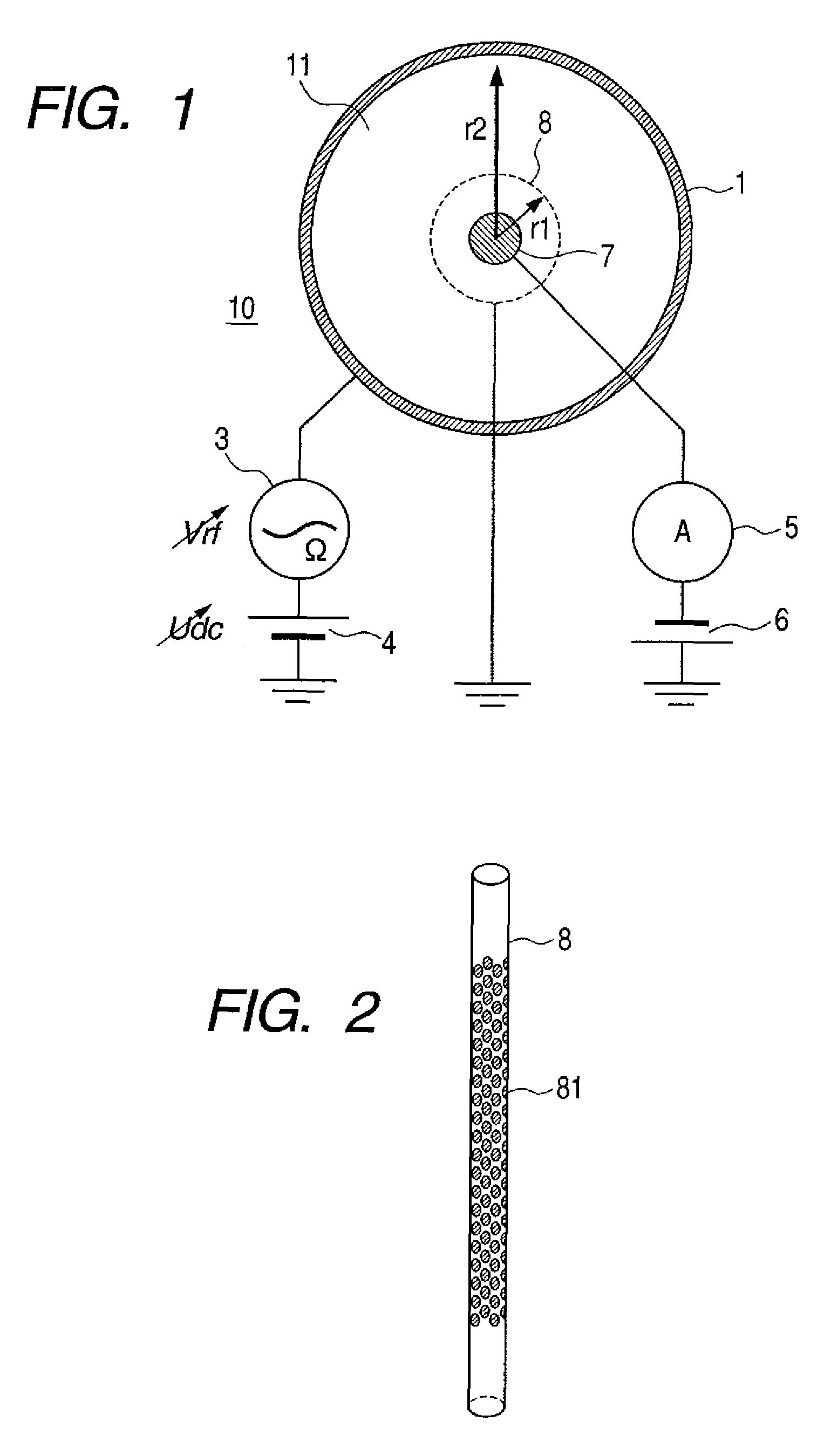
[0019]The first embodiment of this invention is described next while referring to the present invention. FIG. 1 is a drawing for describing an example of the basic circuit and the electrode structure of the one dimensional ion trap of this embodiment. The example shown here utilizes a hollow-cylindrical one dimensional ion trap 10, and is described by utilizing a cross sectional view intersecting the center axis of that ion trap 10.

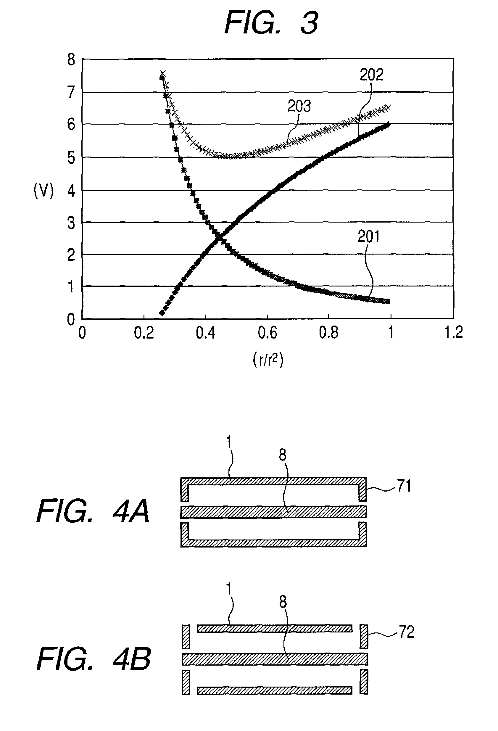
[0020]As shown in this drawing, the one dimensional ion trap 10 of this embodiment includes a first electrode (hollow-cylindrical electrode: radius r2) 1, and a second electrode (mesh hollow-cylindrical electrode: radius r1 (r12) 8, and a third electrode (solid-cylindrical electrode) 7 installed on the inner side of the second electrode. The hollow-cylindrical electrode 1 and the mesh hollow-cylindrical electrode 8 and the Solid-cylindrical electrode 7 are each a hollow cylindrical shape, and are positioned along a joint center axis. An RF voltage (amplit...

second embodiment

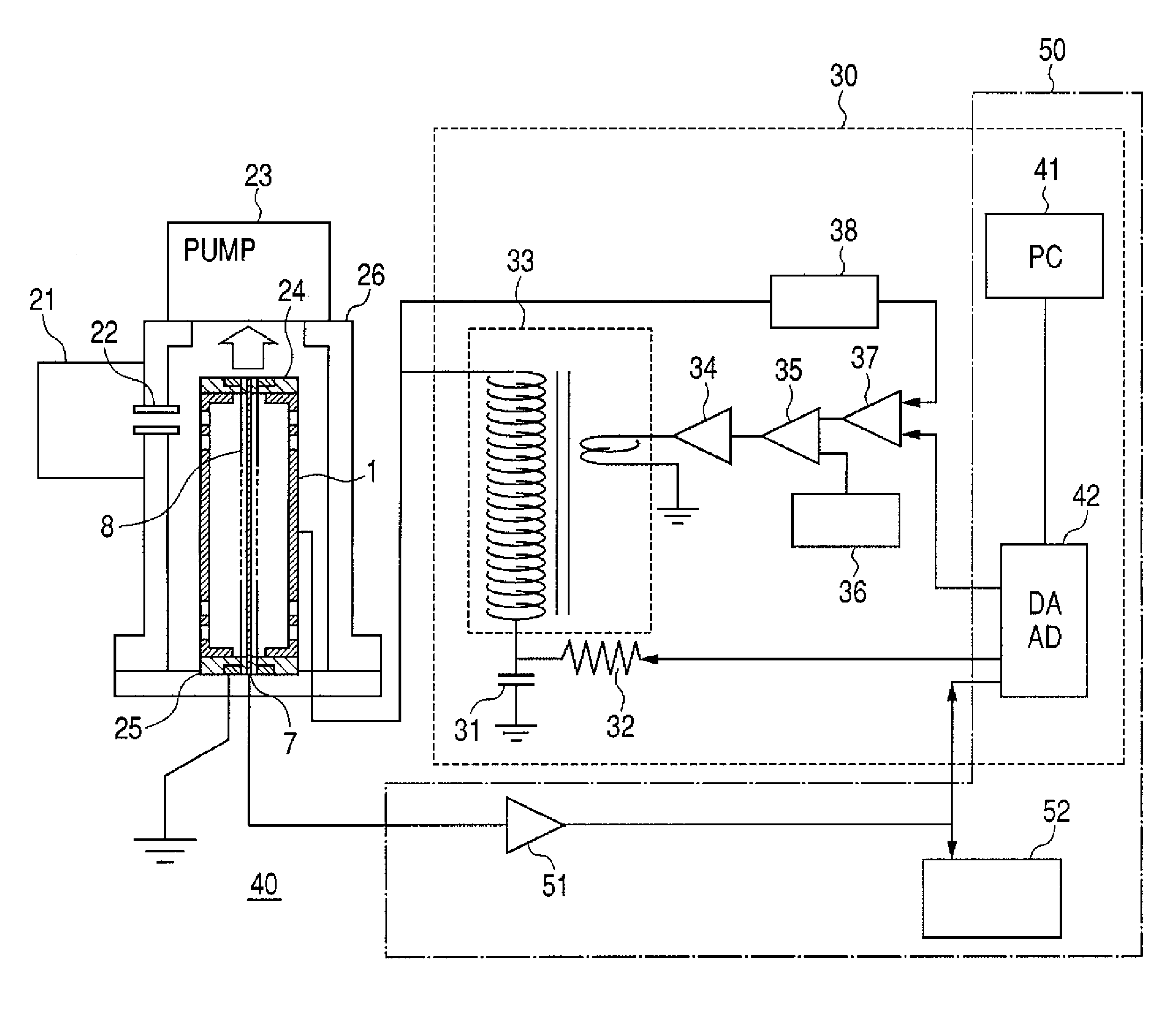
[0065]The second embodiment of this invention is described next. Here the one dimensional ion trap 10 of the first embodiment utilized in the mass spectrometer makes use of ion instability brought about by trap conditions. Namely, the voltage conditions of stably trapped ions are changed to bring about an unstable state, and the ions made to strike the Solid-cylindrical electrode 7 (selectively according to mass) at each mass-to-charge ratio (m / z). The electrical current resulting from the collision is measured by the ammeter 5, and the mass and mass-to-charge ratio (m / z) of the trapped ions are measured.

[0066]In order to selectively pass the ions trapped in the one dimensional ion trap 10 through the mesh hollow-cylindrical electrode 8 according to their mass, at least one of either the static voltage Udc and the amplitude of the RF waves applied by the RF voltage Vrf is changed as described in the first embodiment.

[0067]A structural drawing of the mass spectrometer 40 of this embo...

third embodiment

[0093]The third embodiment of this invention is described next. The one dimensional ion trap 10 of the first embodiment is utilized here for measuring ion mobility (extent of ion movement). The structure of the equipment is fundamentally the same as shown for the second embodiment in FIG. 5 through FIG. 7.

[0094]The method for measuring ion mobility by using the one dimensional ion trap 10 of this embodiment is described next. The mass-to-charge ratio (m / z) of the ion type forming the target is first of all isolated using the technique described in the first embodiment. Mass spectroscopy and measurements may then be made at the mass-to-charge ratio (m / z) of the ion type forming the target with the technique previously described in the second embodiment. A RF voltage Vrf that was set to a high amplitude is next applied so that these isolated ions are trapped in proximity to the outer side in the trapping space 11 of the one dimensional ion trap 10. Applying this RF voltage Vrf has the...


PUM


Abstract

A compact, low-cost, and simple ion trap capable of operating at a low vacuum level is provided along with technology for utilizing that ion trap to perform mass spectroscopy and analyzing ion mobility without a drop in measurement accuracy. Ions are trapped in a one dimensional potential formed by a potential comprised of a direct current voltage and a potential comprised of an alternating current voltage. The trapped ions are made to collide with an electrode by changing at least the applied direct current voltage or alternating current voltage, and are detected as an electrical current value.

Description

CLAIM OF PRIORITY[0001]The present application claims priority from Japanese patent application JP 2008-104487 filed on Apr. 14, 2008, the content of which is hereby incorporated by reference into this application.FIELD OF THE INVENTION[0002]The present invention relates to technology for mass spectroscopy to identify molecules within a sample by measuring the charge to mass ratio of the charged particles. This invention relates in particular to technology for trapping charged particles.BACKGROUND OF THE INVENTION[0003]A method called mass spectroscopy is capable of identifying a sample by measuring the ratio of mass to electrical charge (mass-to-charge ratio: m / z) in a sample enveloped within electrical charges such as ions within a magnetic field. A typical device and method for mass spectroscopy currently in wide use is the ion trap which captures ions within a trap made up of electrodes and then selectively emits ions by changing the electrical potential within the trap.[0004]An...

Claims


Application Information

Patent Timeline
Patent Type & Authority Patents(United States)
IPC IPC(8): H01J49/26B01D59/44
CPCH01J49/4245
Inventor NAGANO, HISASHIBABA, TAKASHISATAKE, HIROYUKI
Owner HITACHI LTD
Why Eureka
Try Eureka