System for successively uncovering ports along a wellbore to permit injection of a fluid along said wellbore

a wellbore and port technology, applied in the field of multi-stage liners, can solve the problems of restricting the production of hydrocarbons, reducing the flow rate, and less efficient operations, and achieve the effect of maximizing the production and flow rate of hydrocarbons

Active Publication Date: 2016-10-27
SC ASSET CORP
View PDF0 Cites 4 Cited by
  • Summary
  • Abstract
  • Description
  • Claims
  • Application Information

AI Technical Summary

Benefits of technology

[0018]It is a further object of the present invention, in certain embodiments thereof, to provide a system which may selectively open groups of continuous ports along a tubing liner separately, to allow separate and discrete fracking of various differently-located hydrocarbon zones which may exist along a length of a tubing liner within a wellbore in a hydrocarbon formation.
[0019]It is a still further object of the present invention to provide a system which can do each of the above, yet nevertheless provide a minimum restriction to the bore of the tubing liner to thereby maximize production and flow rate of hydrocarbon therefrom.
[0020]It is a still further object of certain embodiments of the present invention to be able to accomplish each of the foregoing objects, yet nonetheless not have to, after the completion of the opening of the ports and the fracking process, insert a reamer to ream out any remaining flow obstructions within the tubing liner, and thereby avoid additional steps prior to being able to produce hydrocarbons from a wellbore.
[0029](c) a shear pin, releasably securing said plug member to an uphole end of said collet sleeve, shearable when a force is applied to said plug member to cause said plug member to move downhole in said collet sleeve to a second position therein preventing said protuberance from thereafter being forcibly inwardly compressed and thereby maintaining said protuberance in mating engagement with said circumferential groove;
[0036]In a still further refinement, the plug member is dissolvable, and after moving to said second position and after a period of time being exposed to fluid within said bore, becomes dissolved. Such advantageously avoids having to insert a downhole reamer within the tubing liner, once fluid injection into the formation via the opened ports has been completed, in order to ready the tubing liner for production so as to allow hydrocarbons from locations further downhole to flow uphole to surface.

Problems solved by technology

Many of such tools and systems require components within the bore of the liner at each valve which disadvantageously restricts flow of fluid through the liner during fracture pumping operations, and also, to the extent such systems or remnants thereof remain, similarly restrict production of hydrocarbons.
Due to such flow restrictions, pressure drops occur, which result in less efficient operations as there is pressure loss incurred prior to the fracture fluid contacting the zone.
In addition, such tools and methods require milling out of such components at each valve location prior to switching to production flow from the hydrocarbon bearing zones.
This invention requires, however, a ball seat corresponding to each sleeve in a cluster valve, potentially restricting flow.
The presence of a ball seat at each valve to be opened, due to the resulting bore restriction at each valve sleeve, creates a significant pressure drop across the cluster valve assembly.
However, such designs are not without their own unique drawbacks.
The necessity for seals around dogs 351 necessarily introduces added mechanical complexity and the possibility of inability to release sleeve 322 from engagement if such seals were to leak due to the then-inability to create a pressure differential.
Disadvantageously, only one dart can open one port, and thus a plurality of contiguously spaced ports are not capable of being opened by a single dart using such apparatus / method, thereby rendering such system / method time consuming.

Method used


Image

  • System  for successively uncovering  ports along a wellbore to permit injection of a fluid along said wellbore
  • System  for successively uncovering  ports along a wellbore to permit injection of a fluid along said wellbore
  • System  for successively uncovering  ports along a wellbore to permit injection of a fluid along said wellbore

Examples


Embodiment Construction

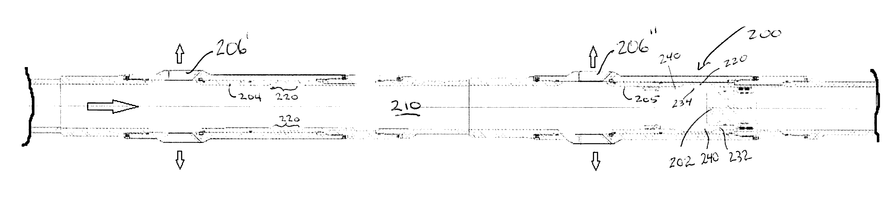
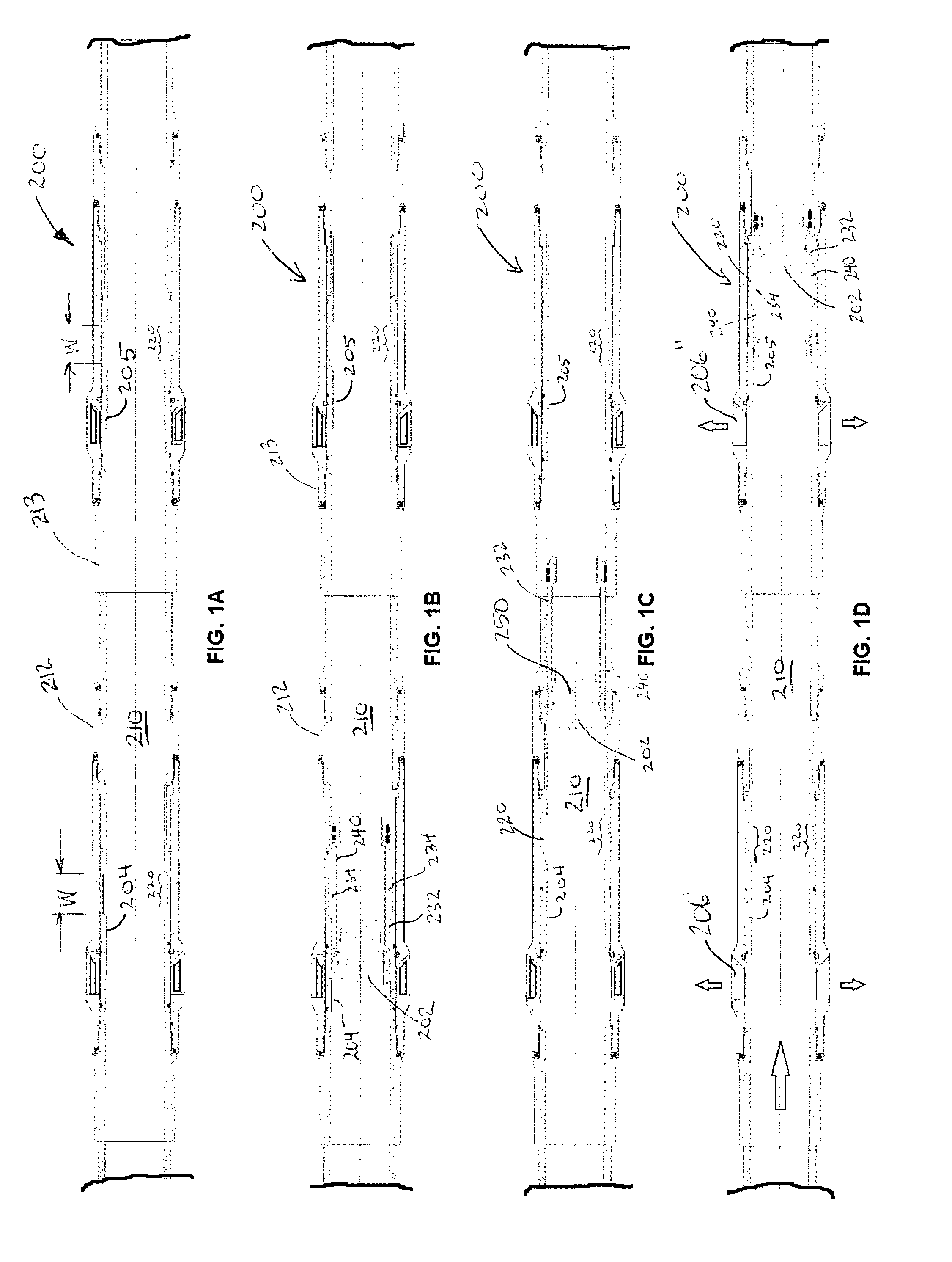
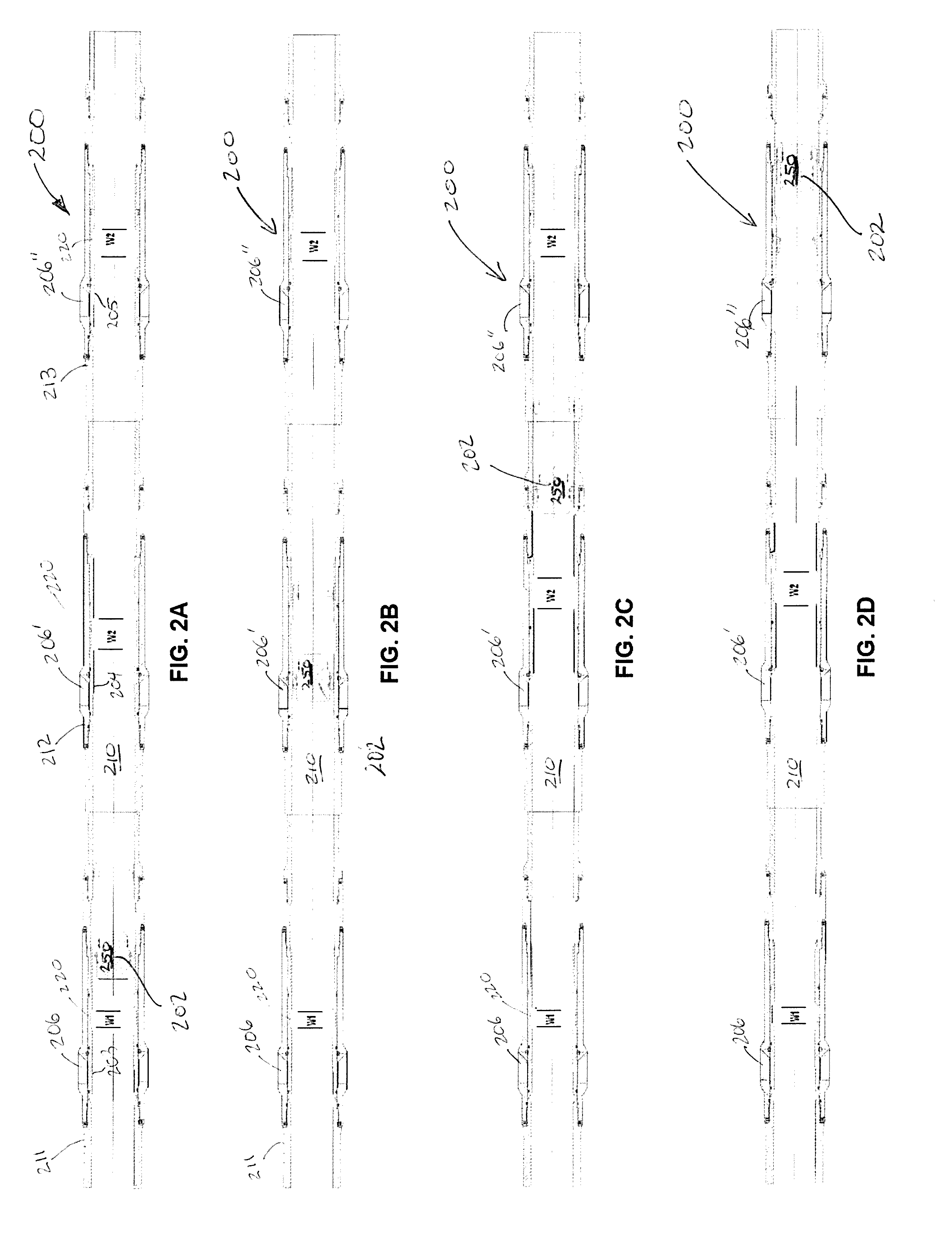
[0085]In the following description, similar components in the drawings are identified with corresponding same reference numerals.

[0086]The system of the present invention is to be used in the conditioning of a wellbore (i.e. “completion” of a wellbore in oilfield parlance) prior to production of hydrocarbons from such wellbore.

[0087]Specifically, the present system can advantageously be used to provide and allow the injection of pressurized fluid into a hydrocarbon-bearing formation at desired optimal locations along the wellbore, for the purposes of initially fracturing the hydrocarbon formation and / or injecting flow-enhancing agents into the formation (such as acids, flow enhancing agents, and / or proppants) all for the purpose and objective of increasing the rate and quantity of hydrocarbons to be subsequently recovered from the hydrocarbon formation.

[0088]A tubing liner 200 inserted into a drilled wellbore serves a variety of purposes, one of which is the reinforcement of the wel...


PUM


Abstract

A system for successively uncovering a plurality of contiguous ports in a tubing liner within a wellbore, or for successively uncovering individual groups of ports arranged at different locations along the liner, to allow successive fracking of the wellbore at such locations. Sliding sleeves in the tubing liner are successively moved from a closed position covering a respective port to an open position uncovering such port by an actuation member placed in the bore of the tubing liner. Each actuation member comprises a dissolvable plug retained by shear pins at an uphole end of a collet sleeve, the latter having radially-outwardly biased protuberances (fingers) which matingly engage sliding sleeves having cylindrical grooves therein, based on the width of the protuberance. When actuating the most downhole sleeve, the shear pin shears allowing the plug to move in the collet sleeve and prevent the protuberance (fingers) from disengaging.

Description

CROSS-REFERENCE[0001]This application claims the benefit of priority from commonly-assigned U.S. patent application Ser. No. 14 / 505,384 filed Oct. 2, 2014, corresponding to Canadian Patent Application CA 2,867,207 filed Oct. 3, 2014 and published Dec. 16, 2014, both of which are entitled “MULTI-STAGE LINER WITH CLUSTER VALVES AND METHOD OF USE” and incorporated herein by reference.FIELD OF THE INVENTION[0002]The present invention relates to multi-stage liners used in open hole or cased completions for injection of fluids at multiple contiguous locations along a wellbore to create multiple fractures in a hydrocarbon zone along the wellbore.BACKGROUND OF THE INVENTION[0003]This background and documents mentioned below are provided for the purpose of making known information believed by the applicant to be of possible relevance to the present invention, and in particular allowing the reader to understand advantages of the invention over devices and methods known to the inventor, but no...

Claims


Application Information

Patent Timeline
Patent Type & Authority Applications(United States)
IPC IPC(8): E21B34/12E21B34/06
CPCE21B34/12E21B2034/007E21B34/063E21B2200/06E21B34/142E21B43/26E21B43/12E21B33/146
Inventor NORDHEIMER, DAVID
Owner SC ASSET CORP
Why Eureka
Try Eureka