
Device and Method For Gas Lock Detection In An Electrical Submersible Pump Assembly

a technology of electrical submersible pumps and gas lock detection, which is applied in the direction of survey, instruments, borehole/well accessories, etc., can solve the problems of delay in production, damage to the motor or nuisance shut down, and delay in production, so as to improve efficiency and reliability in production.

Active Publication Date: 2009-10-08
BAKER HUGHES INC
View PDF2 Cites 52 Cited by
  • Summary
  • Abstract
  • Description
  • Claims
  • Application Information

AI Technical Summary

Benefits of technology

[0012]Once the occurrence of gas lock is detected, embodiments of the present invention can, for example, break the occurrence of gas lock. The method can include, for example, maintaining a pump operating speed. Maintaining a pump operating speed allows the well fluid to remain above the pump in a static condition and allows the gas bubbles in the fluid to rise above the fluid, facilitating a separation of gas and liquid above the pump. After a waiting period of a predetermined duration, the pump operating speed is reduced to a predetermined value defining a flush value, thereby allowing the well fluid to fall back through the pump, flushing out the trapped gas. After a predetermined flush period, the pump operating speed is restored to the previously maintained speed. The embodiments of the present invention have the ability to flush the pump and return the system back to production without requiring system shutdown. In a preferred embodiment, the waiting period is between about 6 to 7 minutes, the flush period is between about 10 and 15 seconds, and the pump operating speed is reduced during the flush period to between about 20 and 25 Hz.
[0013]In addition, embodiments of the present invention provide for an algorithm for optimizing an operating speed of the electrical submersible pump assembly to maximize production without need for operator intervention. The algorithm increases the pump operating speed by a predetermined increment, e.g., 0.1 Hz, up to a preset maximum pump operating speed, e.g., 62 Hz, when the instantaneous value is continually above the threshold value for a predetermined stabilization period, e.g., 15 minutes. The algorithm decreases the pump operating speed by a predetermined increment, e.g., 0.1 Hz, if the instantaneous value is continually below the threshold value for a predetermined initialization period, e.g., 2 minutes.
[0014]Embodiments of this invention have significant advantages. Example embodiments provide the ability to reliably detect a gas lock, without operator intervention, based upon surface data and / or downhole data. Also, example embodiments have the ability to break a gas lock once detected, without requiring the system to be shut down, improving efficiency and reliability in the production of subterranean wells.

Problems solved by technology

It is well known that gas lock can occur when an ESP ingests sufficient gas so that the ESP can no longer pump fluid to the surface due to, for example, large gas bubbles in the well fluid.
Failure to resolve a gas-locked ESP can result in overheating and premature failure.
This wait time represents lost production.
It is also known that there are many methods for determining the proper low current threshold and that an unsatisfactory threshold can result in either damage to the motor or nuisance shut downs.

Method used


Image

  • Device and Method For Gas Lock Detection In An Electrical Submersible Pump Assembly
  • Device and Method For Gas Lock Detection In An Electrical Submersible Pump Assembly
  • Device and Method For Gas Lock Detection In An Electrical Submersible Pump Assembly

Examples


Embodiment Construction

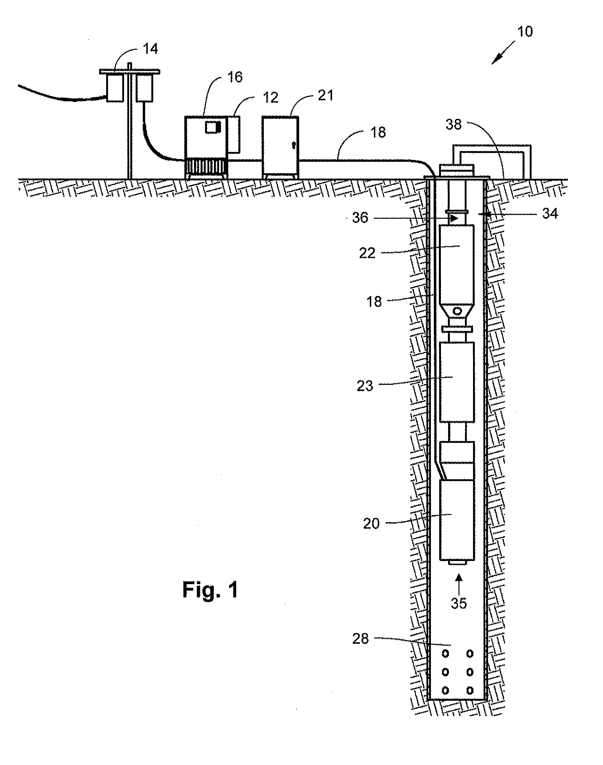
[0023]The present invention will now be described more fully hereinafter with reference to the accompanying drawings in which embodiments of the invention are shown. This invention may, however, be embodied in many different forms and should not be construed as limited to the illustrated embodiments set forth herein; rather, these embodiments are provided so that this disclosure will be thorough and complete, and will fully convey the scope of the invention to those skilled in the art. Like numbers refer to like elements throughout.

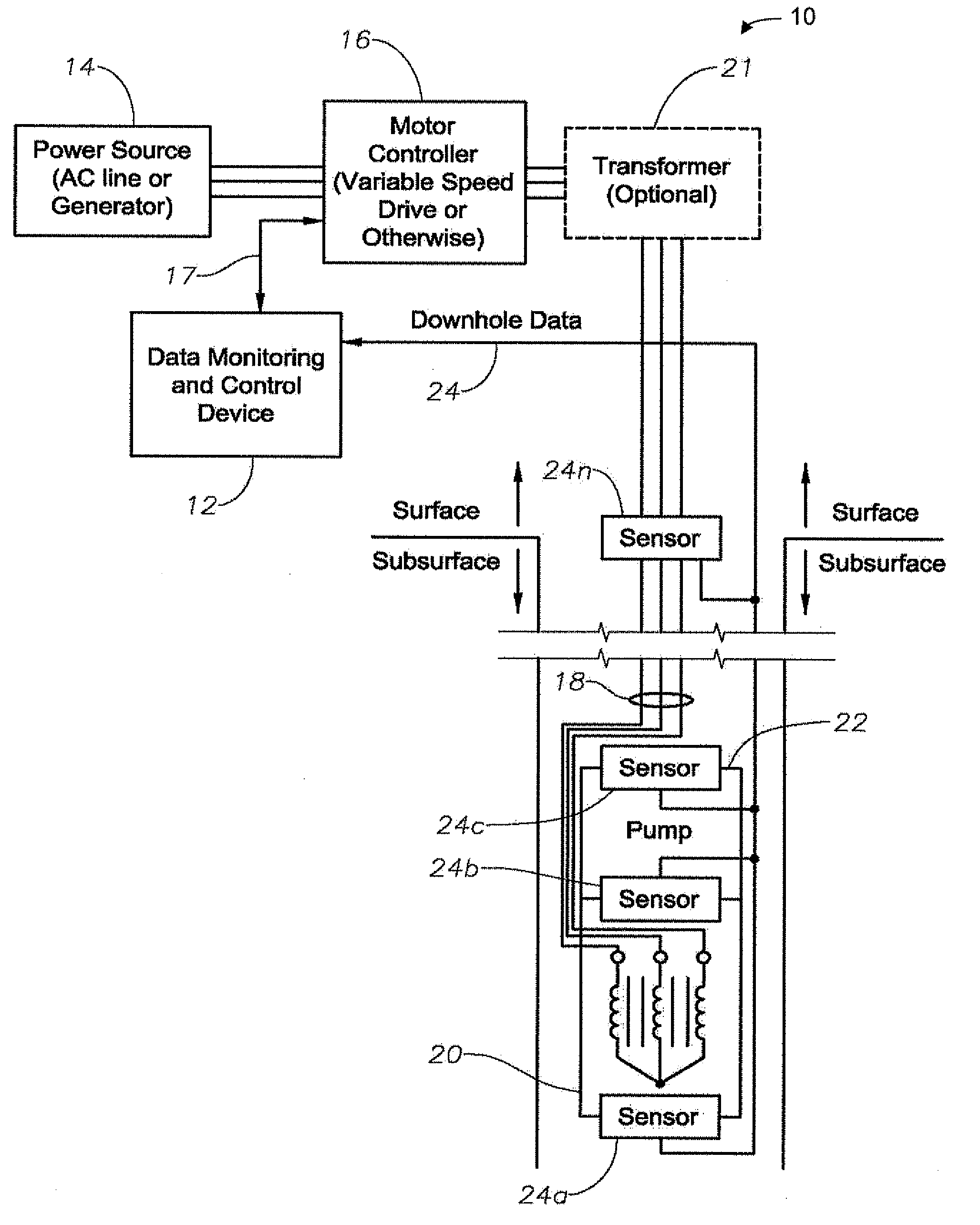
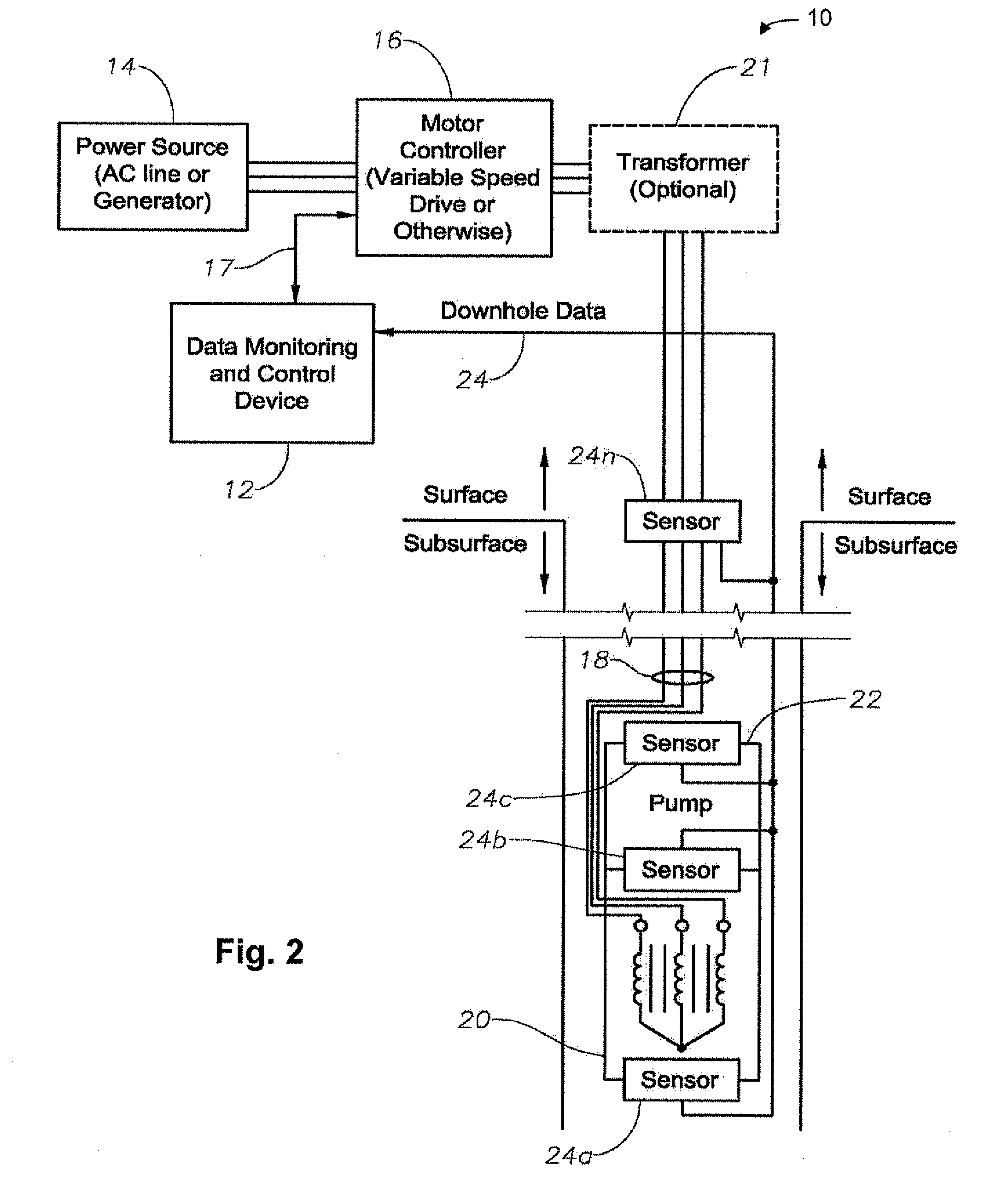
[0024]Embodiments of the present invention can detect an occurrence of gas lock in an electrical submersible pump assembly by monitoring via a sensor an instantaneous value of a property of a fluid associated with an electrical submersible pump assembly and comparing the instantaneous value to a threshold value over a predetermined duration by a controller. Properties of a fluid include conditions, such as, pressure, a differential pressure, temperature, ...


PUM


Abstract

A device and method can detect, and also break, an occurrence of gas lock in an electrical submersible pump assembly in a well bore based upon surface or downhole data without the need for operator intervention. To detect an occurrence of gas lock, an instantaneous value is monitored using a sensor. Then a controller compares the instantaneous value to a threshold value over a predetermined duration to thereby detect the occurrence of gas lock in the electrical submersible pump assembly. Sensors can include, for example, a differential pressure gauge, a pressure gage located in a pump stage located toward the inlet, a fluid temperature sensor located toward the discharge, a free gas detector located near the pump discharge, an electrical resistivity gage, a flow meter located within surface production tubing, and a vibration sensor attached to a tubing string to measure a vibration signature.

Description

RELATED APPLICATIONS[0001]This application is a continuation-in-part of co-pending U.S. patent application Ser. No. 12 / 144,092, by Leuthen et al., titled “Device, Method and Program Product to Automatically Detect and Break Gas Locks in an ESP” filed on Jun. 23, 2008, which claims priority to U.S. Provisional Patent Application No. 60 / 946,190, by Leuthen et al., titled “Device, Method and Program Product to Automatically Detect and Break Gas Locks in an ESP” filed on Jun. 26, 2007, all of which are each incorporated herein in their entireties.BACKGROUND[0002]1. Field of Invention[0003]The present invention relates, in general, to improving the production efficiency of subterranean wells and, in particular, to a device and method which automatically detects gas locks in an electrical submersible pump assembly (“ESP”).[0004]2. Description of the Prior Art[0005]It is well known that gas lock can occur when an ESP ingests sufficient gas so that the ESP can no longer pump fluid to the su...

Claims


Application Information

Patent Timeline
IPC IPC(8): E21B43/12E21B47/00E21B43/00G06F19/00
CPCE21B43/128F04D9/001F04D15/0209F04D15/0066F04D15/0088F04D13/10E21B47/008
Inventor ALLEN, ROBERT D.LEUTHEN, JOHN MICHAELKNOX, DICK L.RIDER, JERALD R.YOHANAN, TOM G.WILSON, BROWN L.SCHULZE, BRYAN D.
Owner BAKER HUGHES INC
Learn More