Apparatus for hydroelectric power production expansion

a technology of hydroelectric power and apparatus, applied in the direction of machines/engines, renewable energy generation, greenhouse gas reduction, etc., can solve the problem of ineffective spin turbines, achieve the effect of minimizing life-cycle costs, minimizing tailwater elevation, and minimizing power production

Inactive Publication Date: 2009-01-20
KELLY WILLIAM LOWELL
View PDF46 Cites 49 Cited by
  • Summary
  • Abstract
  • Description
  • Claims
  • Application Information

AI Technical Summary

Benefits of technology

[0007]The turbine / generator units include both submerged and floatable types, are distinctive and comparatively selected by performance factors matched to hydropower and afterbay conditions of the particular dam whose hydroelectric power production is expanded by the present invention. Sound support structures are tailored for each turbine / generator unit including appropriate fish protection. A structure and its supported unit become one when various combinations of turbine / generator types plus vertical and horizontal locations of both submerged and floatable units are judged for the most effective combination and arrangement of units to maximize electricity production at lowest life-cycle costs. Coupling submersible and floatable turbine / generator units is one cornerstone of the invention. Most effective utilization of laminar flow distributed between submerged and floatable turbine / generator units depends upon depth of tailwater; efficiency of channel design and construction in creating / maintaining laminar flow; type, size, shape and placement of submerged turbine / generator units whose impact on upper laminar flow utilized by floatable generator / turbine units can vary from minor to major. Shallow tailwater tightens and deep tailwater expands leeway in the design process of selection, placement and relationship of turbine / generator units. The submerged turbine / generator units are located as far below the maximum tailwater elevation as practical to utilize lowermost laminar flow because the invention couples the latter turbine / generator units with barge-mounted electricity generating units that utilize uppermost surface laminar flow. The barge-mounted electricity generating units are, for example, undershot water wheels which are driven by the water's kinetic energy just immediately downstream of the submerged turbine / generator units which themselves disturb the lower laminar flow, yet with little disturbance caused thereby to the upper surface laminar flow under relatively high tailwater depth conditions.
[0008]In this manner the once unsuitable turbulent water emerging from draft tubes is converted into laminar flow that drives both submerged and floatable electricity generating units to create maximum electricity generation under project specific flow rates by minimizing impacts of submerged turbine / generator units on performance of floatable turbine / generator units.
[0011]Construction mostly occurs in relative shallow water; requires limited excavation; channel / compartment components are few; supports, beams and associated steel or concrete members are either readily available or can be pre-fabricated on site; or in concrete casting facilities in the region readily moved by truck, rail or barge; and channel / compartments can be assembled concurrently working from readily-relocated solid platforms, such as drill barges with spuds. The invention thereby lends itself to rapid construction that substantially and quickly boosts renewable electricity production at existing hydroelectric dams.

Problems solved by technology

Water emerging from draft tubes is free of debris but roiling and churning renders it ineffective to spin turbines.

Method used


Image

  • Apparatus for hydroelectric power production expansion
  • Apparatus for hydroelectric power production expansion
  • Apparatus for hydroelectric power production expansion

Examples


Embodiment Construction

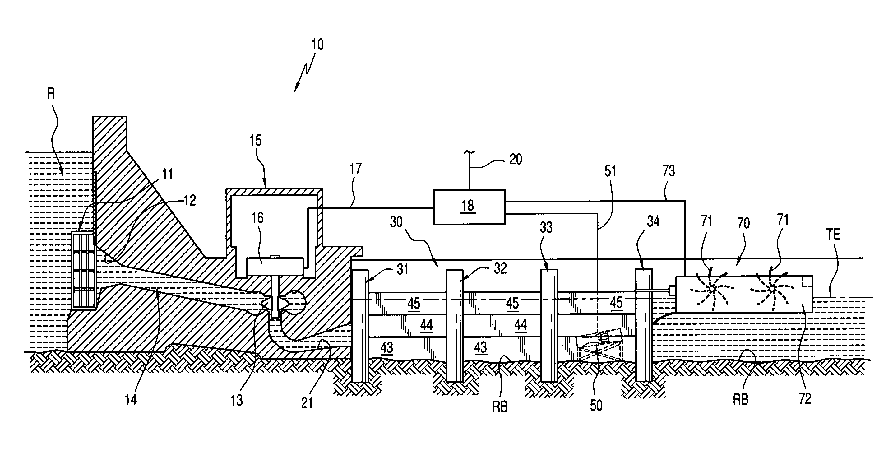
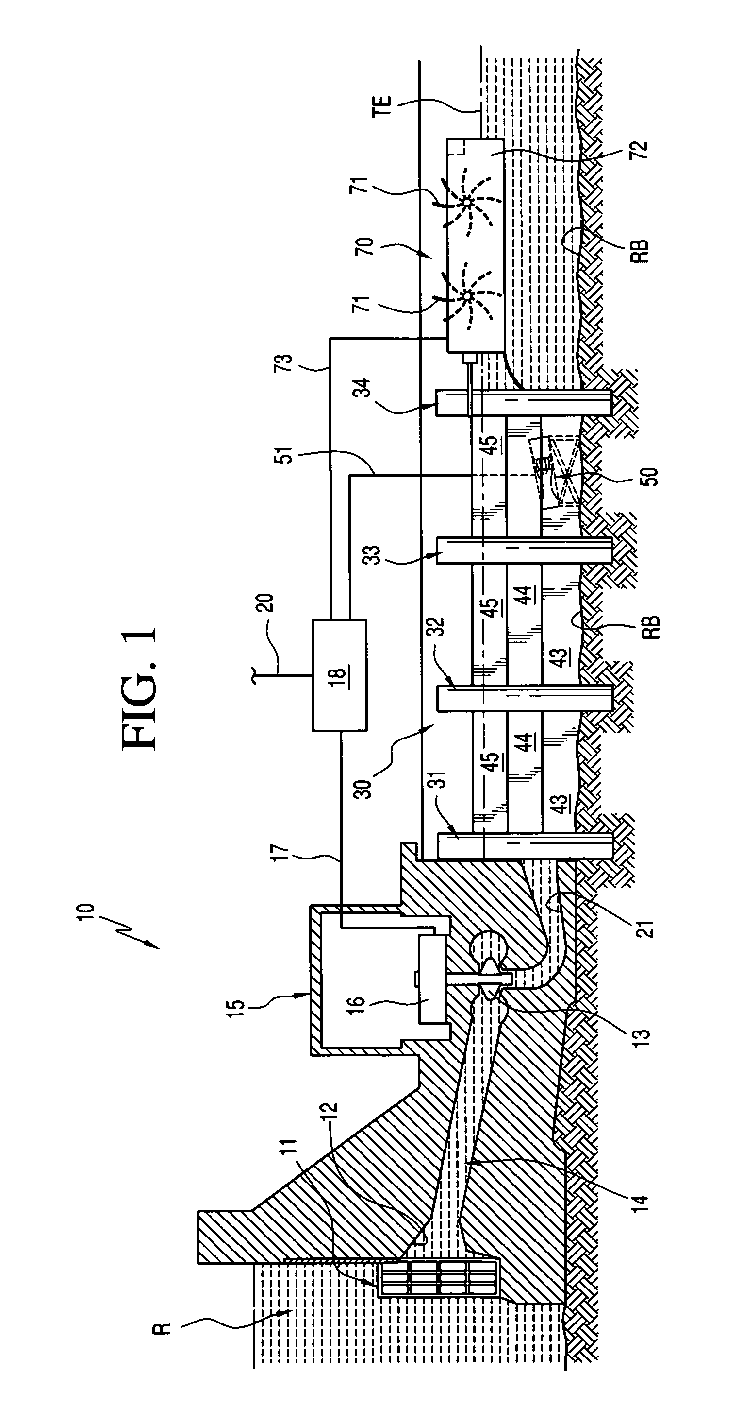
[0022]A conventional hydroelectric dam 10 (FIG. 1) generates electricity through the utilization of water head of its reservoir R. The hydroelectric dam 10 and its associated powerhouse 15 contain from one to several bays per turbine 13. Each bay contains the following elements in various numbers and configurations: trash rack 11, fish screen (not shown), gated intake 12, and penstock 14, which together control and transfer water flow through the turbine 13 to generate torque that transfers to a generator 16 whose electricity is transmitted by power lines 17 to a power system 18 and from the latter via power lines 20 to sources of utilization. Many dams use multiple intakes 12 and draft tube outlets 21 for each turbine 13 which pass water emerging from the draft tube outlets 21 which is free of debris but its roiling and churning condition renders it unsuitable as a turbine driving power source. Therefore, one the major challenge to utilize tailrace water exiting draft tube outlets ...


PUM


Abstract

Normally hydroelectric dam powerhouses use river flow once before discharging it as turbulent tailwater, ineffective to spin turbines. The present invention uses tapered channels to confine and constrict turbulent tailwater into laminar flow that drives turbines both submersible and floatable utilizing the same water three times concurrently to generate new electricity. Channels originate adjacent to draft tube outlets, constrict in the downstream direction to create narrow necks where turbine / generators benefit from debris free, increased velocity and laminar flows to generate electricity. Hydroelectricity uses zero fuel, creates zero waste and has zero carbon dioxide emissions. Structures are uncomplicated, construction is within project boundaries minimizing environmental impacts and speeding projects coming online. New facilities are protected by existing dam security. Hydroelectricity replaces less dependable renewable energy systems.

Description

BACKGROUND OF THE INVENTION[0001]Applicant / Inventor was a designer for twenty-two years and Value Engineering Officer (hereinafter VEO) for nine years with the Walla Walla District U.S. Army Corps of Engineers. In that period eight new hydroelectric dams were built on the Columbia, Snake, Boise and Clearwater rivers. Applicant / Inventor was involved with several of them and as VEO, he led studies on many until retiring in 1982 to continue his career in Value Engineering (hereinafter VE) as an international consultant. That included occasional VE studies on dams, such as five potential projects in Nepal and several more in the United States.[0002]McNary Dam on the Columbia River is first Applicant / Inventor encountered with the Corps. The 1340 foot long powerhouse has fourteen generators. The total rated capacity of the powerhouse is 1,120,000 kilowatts. One hydropower turbine at McNary Dam produces as much electricity as two hundred and eleven 660 KW wind turbines. In addition, McNary...

Claims


Application Information

Patent Timeline
Patent Type & Authority Patents(United States)
IPC IPC(8): E02B9/00
CPCE02B9/02F03B3/04F03B3/14Y02E10/22Y02E10/223Y02E60/17Y02E10/20Y02E60/16
Inventor KELLY, WILLIAM LOWELL
Owner KELLY WILLIAM LOWELL
Why Eureka
Try Eureka