Retractable vortex generator

a vortex generator and flow control technology, applied in airflow influencers, aircraft stabilisation, transportation and packaging, etc., can solve the problems of affecting the design of the wing or other structure in a negative manner, affecting the proper performance of the aircraft, and cannot be easily retrofitted for such vortex generators. , to achieve the effect of reducing drag

Active Publication Date: 2011-02-01
TEXTRON INNOVATIONS
View PDF32 Cites 51 Cited by
  • Summary
  • Abstract
  • Description
  • Claims
  • Application Information

AI Technical Summary

Benefits of technology

[0013]The flow control device as described provides reduction of drag and ice accumulation on flow control surfaces without requiring space in the flow control device to be reserved for the retracted vortex generators. Thus the retractable vortex generators of the current invention may be applied to a large variety of flow control surfaces without the necessity of extensive retrofitting of the flow control surfaces.

Problems solved by technology

However, permanently installed wing vortex generators produce drag penalties and may accrete foreign matter such as ice shapes that significantly degrade the proper performance of the aircraft.
This requirement for adequate space to accommodate the vortex generators may influence the design of the wing or other structure in a negative manner.
This also requires that a wing, or other such structure having a flow control surface to which a vortex generator is desired to be added cannot be easily retrofitted for such vortex generators.
However in both the deflected and undeflected states the vortex generator protrudes outside of the flow control surface and, while the undeflected state may produce less drag in comparison with the deflected state, the protrusion will still produce some undesirable residual drag and does not alleviate the problem of ice accretion on the exposed vortex generators.

Method used


Image

  • Retractable vortex generator
  • Retractable vortex generator
  • Retractable vortex generator

Examples


Embodiment Construction

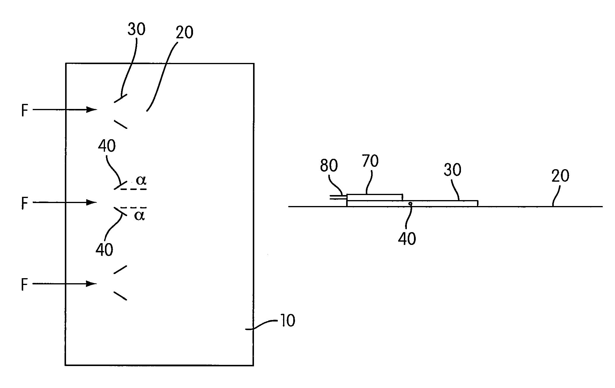
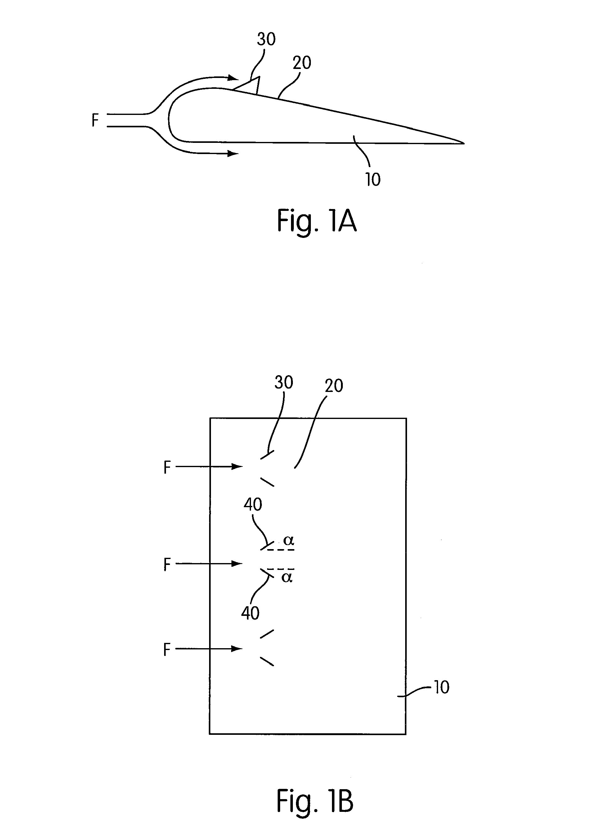
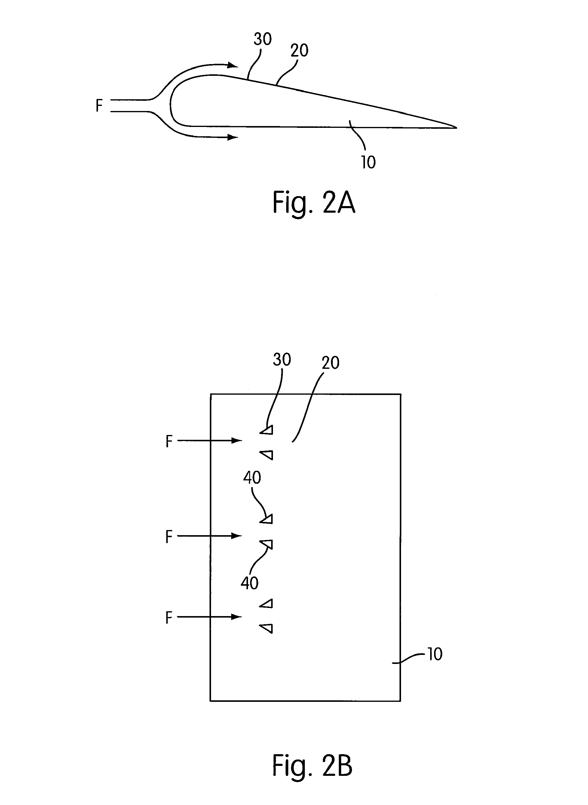
[0023]FIGS. 1A, 1B, 2A, and 2B show an example of a flow control device 10 in accordance with one embodiment of the present invention. FIG. 1A shows a side view and FIG. 1B shows a top view of a flow control surface 20 over which a fluid media is designed to flow in a direction represented by vector F. An array of vortex generators 30 are illustrated in an extended position. Vortex generators 30 are substantially flat structures that are generally perpendicular with respect to the plane of the control surface when extended. Each of the vortex generators 30 are constructed so as to be pivotable about a pivot axis 40. The pivot axis 40 forms an acute angle α with the flow direction (or primary wind direction) F so as to facilitate the generation of a swirling fluid flow. The acute angle α may be between 5 and 45 degrees (or −5 to −45 degrees, depending on the direction measured) to generate vortices over the flow control surface 20. In a more specific embodiment, the angle α is betwee...


PUM


Abstract

A flow control device is disclosed including a flow control surface over which fluid is designed to flow in a predetermined direction. Vortex generators are associated with the flow control surface. Each respective vortex generator has a pivot axis that forms an acute angle with respect to the predetermined direction and is capable of being positioned in both of an extended state, in which the respective vortex generators function to create a swirling fluid flow, and a retracted state, in which the respective vortex generators are pivoted via the pivot axis so as to lie adjacent to the flow control surface. An actuator is associated with each of the vortex generators, each actuator adapted to position the associated vortex generator between the extended and retracted states. The flow control device is disclosed to be used in tiltrotor vehicles.

Description

[0001]The present application claims priority to U.S. Provisional Application Ser. No. 60 / 695,181, filed Jun. 30, 2005, the entirety of which is incorporated herein by reference.BACKGROUND OF THE INVENTION[0002]1. Field of the Invention[0003]This invention relates to flow control surfaces with retractable vortex generators.[0004]2. Description of Related Art[0005]Vortex generators have been used with a variety of flow control surfaces to mix low momentum fluid flow associated with a boundary air layer of the flow control surface with a high momentum fluid flow outside of the boundary air layer. The use of such vortex generators in a variety of aircraft have produced improvements in maneuver effectiveness. However, permanently installed wing vortex generators produce drag penalties and may accrete foreign matter such as ice shapes that significantly degrade the proper performance of the aircraft.[0006]Retractable vortex generators have been developed to compensate for these problems....

Claims


Application Information

Patent Timeline
Patent Type & Authority Patents(United States)
IPC IPC(8): B64C23/06B64C21/00
CPCB64C23/06Y02T50/162Y02T50/10
Inventor NARRAMORE, JIMMY CHARLES
Owner TEXTRON INNOVATIONS
Why Eureka
Try Eureka