
Adjustable handle clamp systems and methods

a technology of adjustable handle and clamp, which is applied in the field of adjustable handle clamp, can solve the problems of user's hands being in an unergonomic position, and it is difficult to mount an auxiliary handle grip onto the handle of the tool, so as to achieve the effect of easily and successfully installing or adjusting the clamp

Inactive Publication Date: 2011-02-08
HIXON WILLIAM K
View PDF12 Cites 19 Cited by
  • Summary
  • Abstract
  • Description
  • Claims
  • Application Information

AI Technical Summary

Benefits of technology

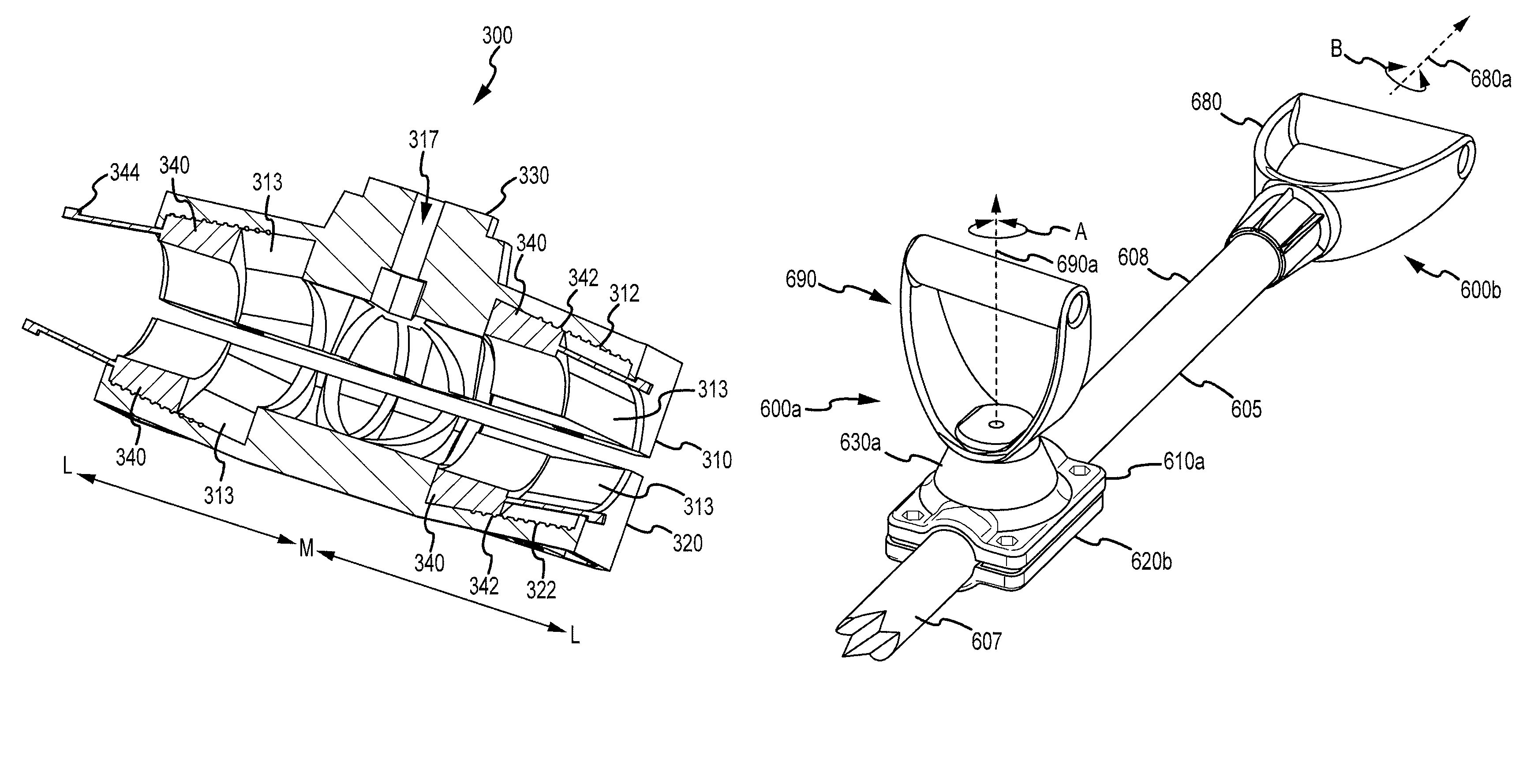
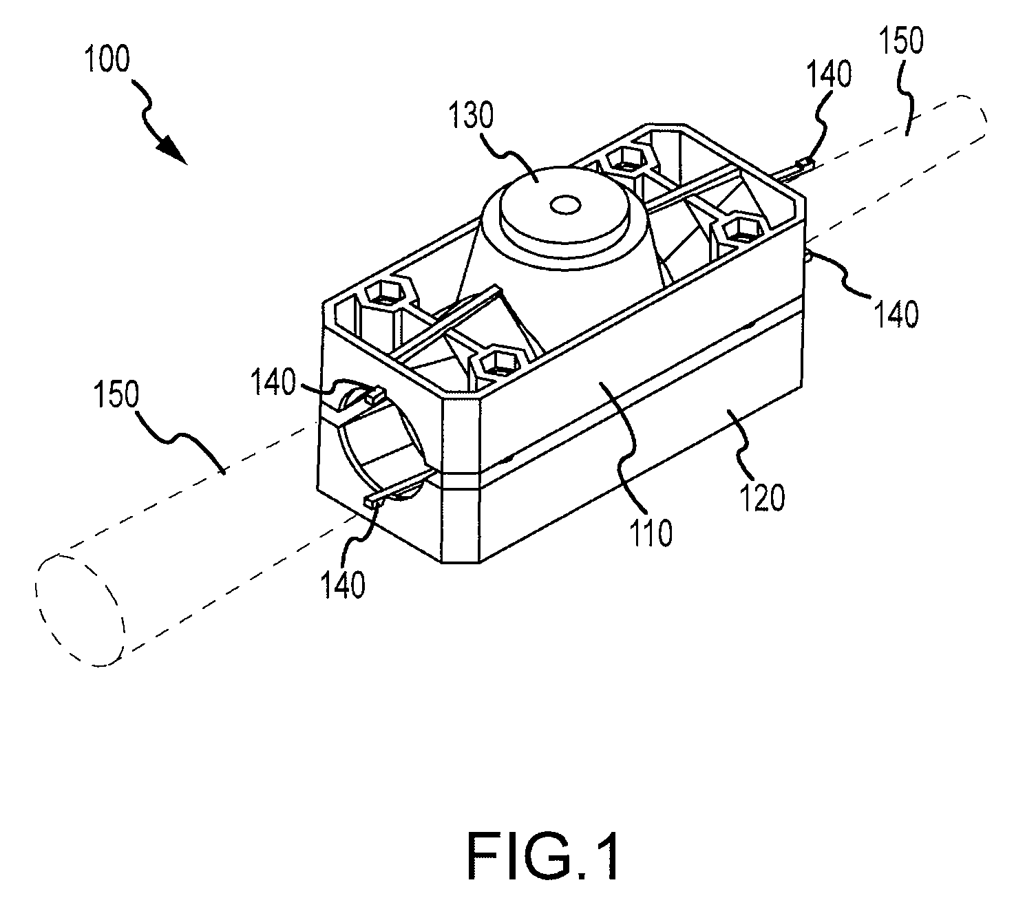
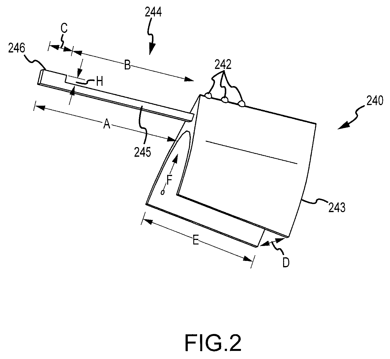
[0004]Embodiments of the present invention encompass clamp devices and methods that can be used for cylindrical objects, substantially cylindrical objects, tapered objects, and other handle designs. Advantageously, such clamps can be used with objects of various sizes or various degrees of taper. Often, the clamp is applied to a cylindrical object such as a broomstick, a shovel handle, a pitchfork handle, and the like. An exemplary clamp can include, for example, a first base, a second base, an attachment for a handle such as a “D” handle, and a plurality of collets. A collet can include raised projections, or stops, which allow the collet to be adjustably positioned within indents of the first and second bases. If the clamp is to be placed on a cylinder having a larger diameter, the collet can be adjusted toward the center of the bases. Conversely, if the clamp is to be placed on a cylinder having a smaller diameter, the collet can be adjusted toward the end of the base. A tapered cylinder can be accommodated by placing one collet toward the base center, and another collet toward the base end. Advantageously, this design allows the tool operator to easily and successfully install or adjust the clamp. Embodiments of the present invention are well suited for use with any of a variety of tools, such as those described in previously incorporated U.S. Pat. Nos. 6,401,833, 6,796,383, and 6,955,228.

Problems solved by technology

Unfortunately, such tools often force the user to have their hands in an unergonomic position.
Yet many hand tools have substantially tapered handles, making it difficult to mount an auxiliary handle grip onto the handle of the tool.

Method used


Image

  • Adjustable handle clamp systems and methods
  • Adjustable handle clamp systems and methods
  • Adjustable handle clamp systems and methods

Examples


Embodiment Construction

[0018]Tool handles and other objects present a variety of different sizes, shapes, and degrees of taper. For example, many wooden handles for common garden tools are substantially tapered in shape or profile. Hand held tools are used to perform a wide variety of functions. For example, these implements are commonly used in outdoor applications, and particularly in the fields of farming, landscaping, digging, excavating, gardening, and cultivation. Examples of hand held tools include rakes, shovels, hoes, spades, pitchforks, scythes, scoops, and the like, including hand held weed and plant harvesting tools.

[0019]Embodiments of the present invention encompass clamp devices and methods that can be used for cylindrical objects or substantially cylindrical objects. Advantageously, such clamps can be used with objects of various sizes or various degrees of taper. Often, the clamp is applied to a cylindrical object such as a broomstick, a shovel handle, a pitchfork handle, and the like. Su...


PUM

PropertyMeasurementUnit
lengthaaaaaaaaaa
lengthaaaaaaaaaa
lengthaaaaaaaaaa

Abstract

An auxiliary handle clamp system includes an upper base, a lower base coupleable with the upper base, a handle attachment coupled with the upper base, and a plurality of adjustable collets coupled with the upper and lower bases.

Description

CROSS-REFERENCES TO RELATED APPLICATIONS[0001]This application is a nonprovisional of, and claims the benefit of priority from, U.S. Provisional Patent Application No. 60 / 889,992 filed Feb. 15, 2007. This application is also related to U.S. Pat. Nos. 6,401,833, 6,796,383, and 6,955,228. The entire content of each of these filings is incorporated herein by reference for all purposes.BACKGROUND OF THE INVENTION[0002]Embodiments of the present invention relate to clamp systems and methods, and in particular to an adjustable clamp that can be adjusted to accommodate cylindrical objects or handles of various sizes or degrees of taper.[0003]Shovels, pitchforks, and other hand tools are useful for performing a variety of tasks. Unfortunately, such tools often force the user to have their hands in an unergonomic position. In some cases, it may be desirable to equip such tools with an auxiliary handle grip to provide ergonomic advantage to the tool operator. Yet many hand tools have substant...

Claims


Application Information

Patent Timeline
Patent Type & Authority Patents(United States)
IPC IPC(8): B25G1/00
CPCA01B1/026B25G1/00B25G3/24Y10T16/516Y10T16/4713Y10T16/469Y10T29/537Y10T16/4559Y10T16/498
Inventor HIXON, WILLIAM K.
Owner HIXON WILLIAM K
Learn More