Insole for a shoe and accessories therefor

a technology for shoes and accessories, applied in the field of shoes and accessories, can solve the problems of little opportunity provided to the purchasers of shoes to change the appearance and overall design of shoes, seen as a significant disadvantage to the purchaser and wearer of these items, and no possibility provided to the purchaser or wearer to modify or vary the light-emitting properties of shoes, so as to achieve the effect of greater freedom of modification and alteration of the appearance of shoes

Inactive Publication Date: 2011-03-22
MIRZA TARIQ +2
View PDF13 Cites 20 Cited by
  • Summary
  • Abstract
  • Description
  • Claims
  • Application Information

AI Technical Summary

Benefits of technology

[0015]The insole may be provided in a range of colors, designs and sizes, thus allowing an existing shoe to be customized by the user with a minimum of alteration to the fabric and structure of the shoe. This allows the same shoe to be customized in a variety of ways and with a variety of designs in a simple and inexpensive way.
[0023]In one preferred embodiment, the insole extension comprises a housing and an insert, the insert having the surface visible from the exterior of the shoe when the shoe is being worn. Most preferably, the insert is readily removable from the housing. In this way, the user is easily able, by exchanging or replacing the insert in the housing, to modify the overall appearance and design of the shoe, in particular the upper. In embodiments where the insole comprises an emitter for light and / or sound, it is preferred that the emitter and any energy storage device are both located within the insert. The controller, if present, may be located in the insole, or in the insert. If the controller is in the insert, it may be preprogrammed to effect the desired display. In such a case, a plurality or set of different inserts may be envisaged for use with a single insole, thus allowing the user to obtain a variety of different display effects simply by exchanging the insert in the housing.
[0032]In a particularly preferred embodiment the insert is removable from the receiver. In this way, the purchaser of the shoe is able to vary the overall appearance and design of the shoe by changing the insert located in the receiver. The shoe may be provided together with a plurality of different inserts. Alternatively, inserts of different designs may be provided separate from the shoe as an accessory.
[0043]The aspects of the invention discussed above relate to a shoe for manufacture and sale with the capability to vary the pattern and design of the shoe. In addition, however, the present invention also provides a means whereby existing shoes can be modified or customized in accordance with the general concept of this invention, such that the appearance and design of a pre-existing shoe may also be readily altered.
[0047]A preferred embodiment of the accessory is one in which the mount comprises a housing, the visible surface being disposed on an insert retained in the housing. In order to allow the user to vary the overall design and appearance of the accessory and the shoe, the insert is preferably removable from the housing. In such cases, any emitters present in the accessory are most preferably located within the insert, together with their energy source. In such cases, the accessory may be provided with a single insert, or, alternatively, a plurality of different inserts, thereby providing the user with greater freedom to modify and alter the appearance of the shoe.

Problems solved by technology

To date, there has been little opportunity provided to the purchasers of shoes to change the appearance and overall design of shoes, once purchased.
Given the high purchase price of many shoes, this can be seen to be a significant disadvantage to the purchaser and wearer of these items.
While such light emitting shoe designs have proven popular, once again there is no possibility provided to the purchaser or wearer to modify or vary the light emitting properties of the shoe.
In addition, should the control device malfunction or the battery become exhausted, the display elements of the shoe are rendered inoperative.

Method used


Image

  • Insole for a shoe and accessories therefor
  • Insole for a shoe and accessories therefor
  • Insole for a shoe and accessories therefor

Examples


Embodiment Construction

[0067]The following detailed description is of the best presently contemplated mode of carrying out the invention. This description is not to be taken in a limiting sense, but is made merely for the purpose of illustrating general principles of embodiments of the invention.

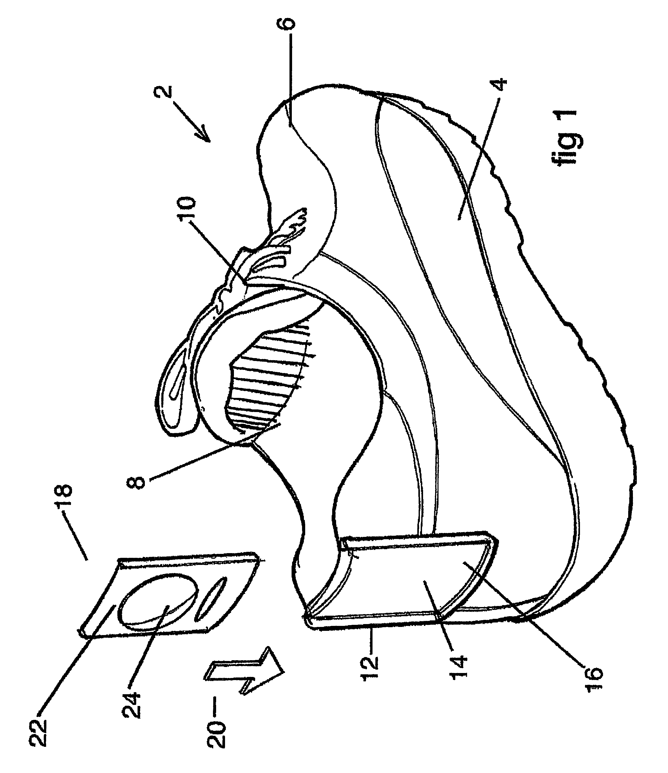
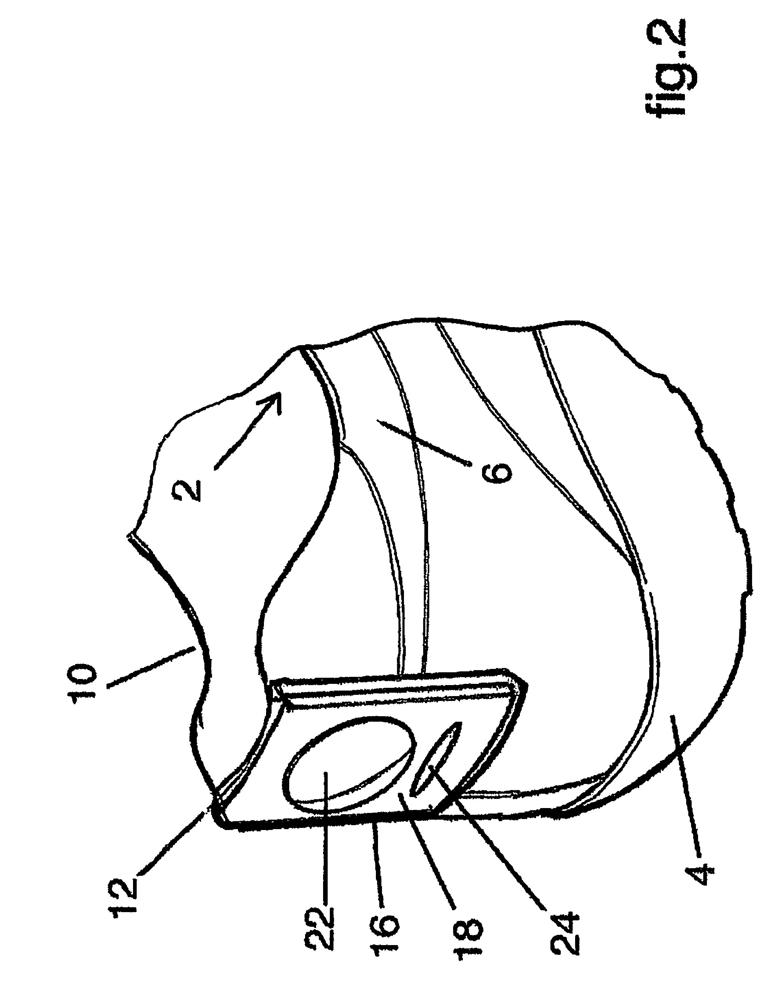
[0068]Referring to FIG. 1, there is shown a training shoe, generally indicated as 2. For ease of reference, the various aspects and embodiments of the present invention will be described and illustrated having reference to a training shoe, such as shown in FIG. 1. However, as noted above, it is to be understood that the aspects and embodiments of the present invention are not limited to training shoes and are readily applicable to other items of footwear.

[0069]The shoe 2 of FIG. 1 has a sole 4 and uppers 6, both of a conventional design and construction. The shoe 2 has an opening 8 defined by an edge of 10 of the uppers 6, into which the foot of the wearer is inserted. Again, these features are of conventional, kn...


PUM


Abstract

An insole (102) for a shoe is provided, having a display surface (116), preferably disposed on an insert, for the display of information when the insole is in place in a shoe. A shoe (10), for example a sports shoe, is also provided having a receiver disposed on its external surface. The receiver retains an insert having a display surface, visible when the shoe is being worn and adapted for the display of information. The display surface may carry a brand or other design and / or emit light or sound by means of a suitable emission device. An accessory for a shoe comprises a mount for securing to a shoe, the mount having a display surface adapted to be visible when the shoe is being worn. The mount preferably holds an insert of the kind mentioned above.

Description

CROSS REFERENCE TO RELATED APPLICATION[0001]This application is a U.S. application filed under 35 USC 111(a) claiming benefit under 35 USC 120 and 365(c) of PCT International Application No. PCT / GB2004 / 003750 filed on Sep. 2, 2004, which is hereby incorporated herein by reference.BACKGROUND OF THE INVENTION[0002]1. Field of the Invention[0003]The present invention relates to shoes and accessories therefore, in particular an accessory for attachment to the exterior of the shoe and an insole for use with the shoe.[0004]2. Description of Related Art[0005]In the present specification, references to a “shoe” or “shoes” are not to be taken as being limited to a single type of footwear, but are to be interpreted as embracing all forms of footwear, including but not limited to shoes, training shoes, sports shoes, such as running shoes and soccer boots, sandals, boots, plimsolls, slippers and the like. Other items of footwear are also embraced by this term, including roller skates, ice skate...

Claims


Application Information

Patent Timeline
Patent Type & Authority Patents(United States)
IPC IPC(8): A43B23/00A43B13/38A43B3/00A43B3/24
CPCA43B1/0036A43B3/0005A43B3/0021A43B3/0078A43B3/24A43B3/242A43B23/24A43B3/50A43B3/34
Inventor MIRZA, TARIQBRODIE, ANDREW NEILAKERS, NOEL JAMES
Owner MIRZA TARIQ
Why Eureka
Try Eureka