Refrigerant expansion assembly with pressure relief

a technology of expansion assembly and refrigerant, which is applied in the field of vehicle air conditioning systems, can solve the problems of insufficient typical expansion device used with conventional refrigerants, easy to break, and complex orifice tube assembly, etc., and achieves the effects of reducing costs, simple, inexpensive and reliable assembly, and simple, inexpensive and reliable design

Inactive Publication Date: 2011-03-29
GM GLOBAL TECH OPERATIONS LLC
View PDF14 Cites 4 Cited by
  • Summary
  • Abstract
  • Description
  • Claims
  • Application Information

AI Technical Summary

Benefits of technology

An advantage of an embodiment is that the refrigerant expansion assembly has both an orifice bypass valve to relieve high pressure upstream of the orifice, and a pressure relief valve that will release refrigerant pressure when the pressure is high enough that damage to the evaporator is possible—all in a relatively simple, inexpensive and reliable assembly. The pressure relief is particularly useful when employing refrigerants that operate at a higher pressure than conventional vehicle refrigerants, such as, for example, carbon dioxide refrigerant systems. The orifice bypass valve is a simple, inexpensive and reliable design for achieving the desired pressure relief.
An advantage of an embodiment is that a refrigerant filter member is removable for service, thus reducing costs associated with assembly and servicing of a clogged filter.
An advantage of an embodiment is that the refrigerant expansion assembly includes a compact design with four parallel port connections, thus allowing for easier packaging in the vehicle.

Problems solved by technology

With these much higher pressures, the typical expansion devices used with the conventional refrigerants are not adequate.
Accordingly, some have modified thermal expansion valves to operate at the higher pressures of the new refrigerants, but drawbacks exist with the diaphragm located in the thermal expansion valve between the inflow refrigerant stream and the outflow refrigerant stream, and with a tube used for a temperature sensor, which is easily broken during assembly.
But this orifice tube assembly is overly complex and expensive to fabricate and assemble.

Method used


Image

  • Refrigerant expansion assembly with pressure relief
  • Refrigerant expansion assembly with pressure relief
  • Refrigerant expansion assembly with pressure relief

Examples


first embodiment

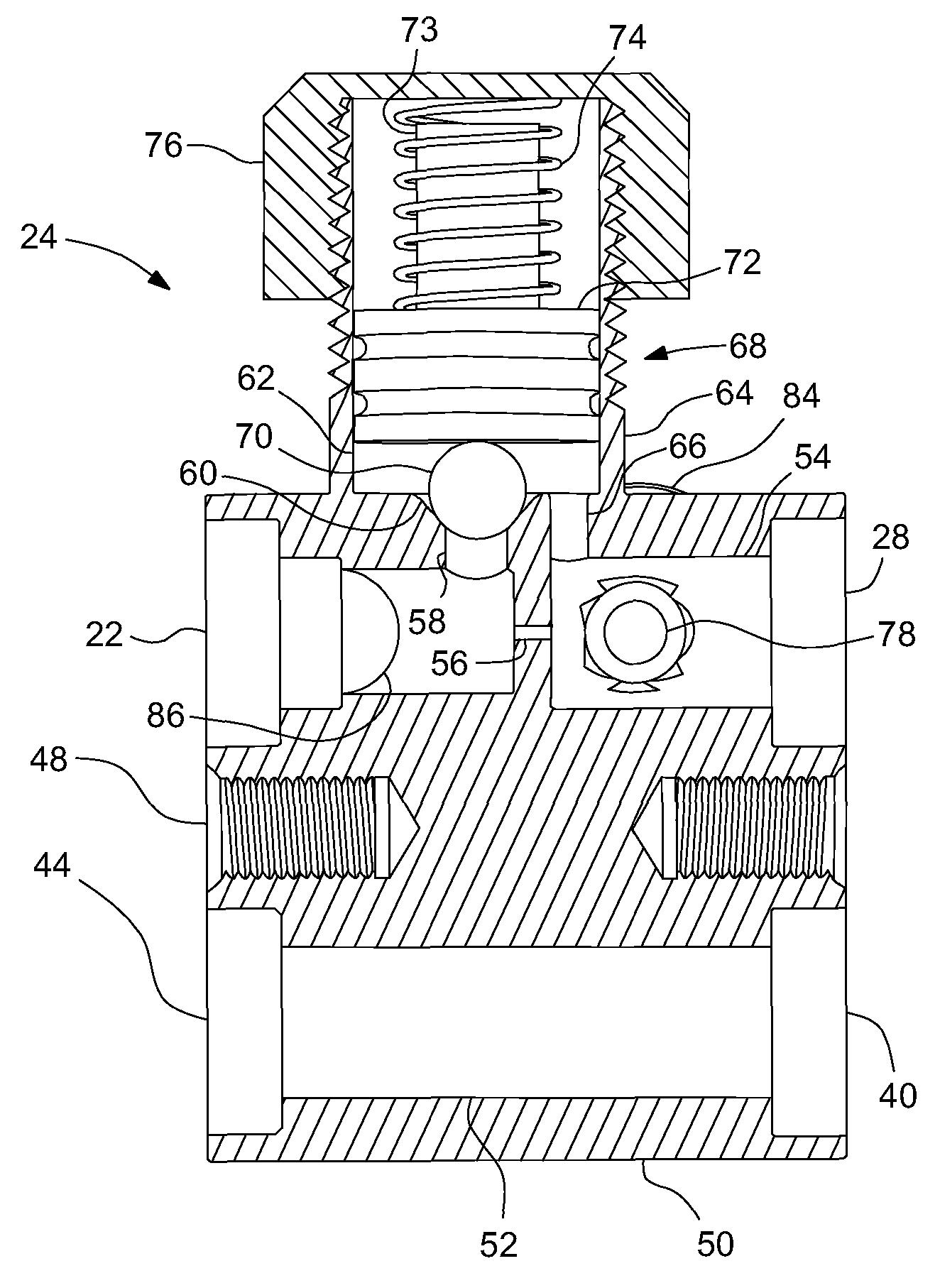
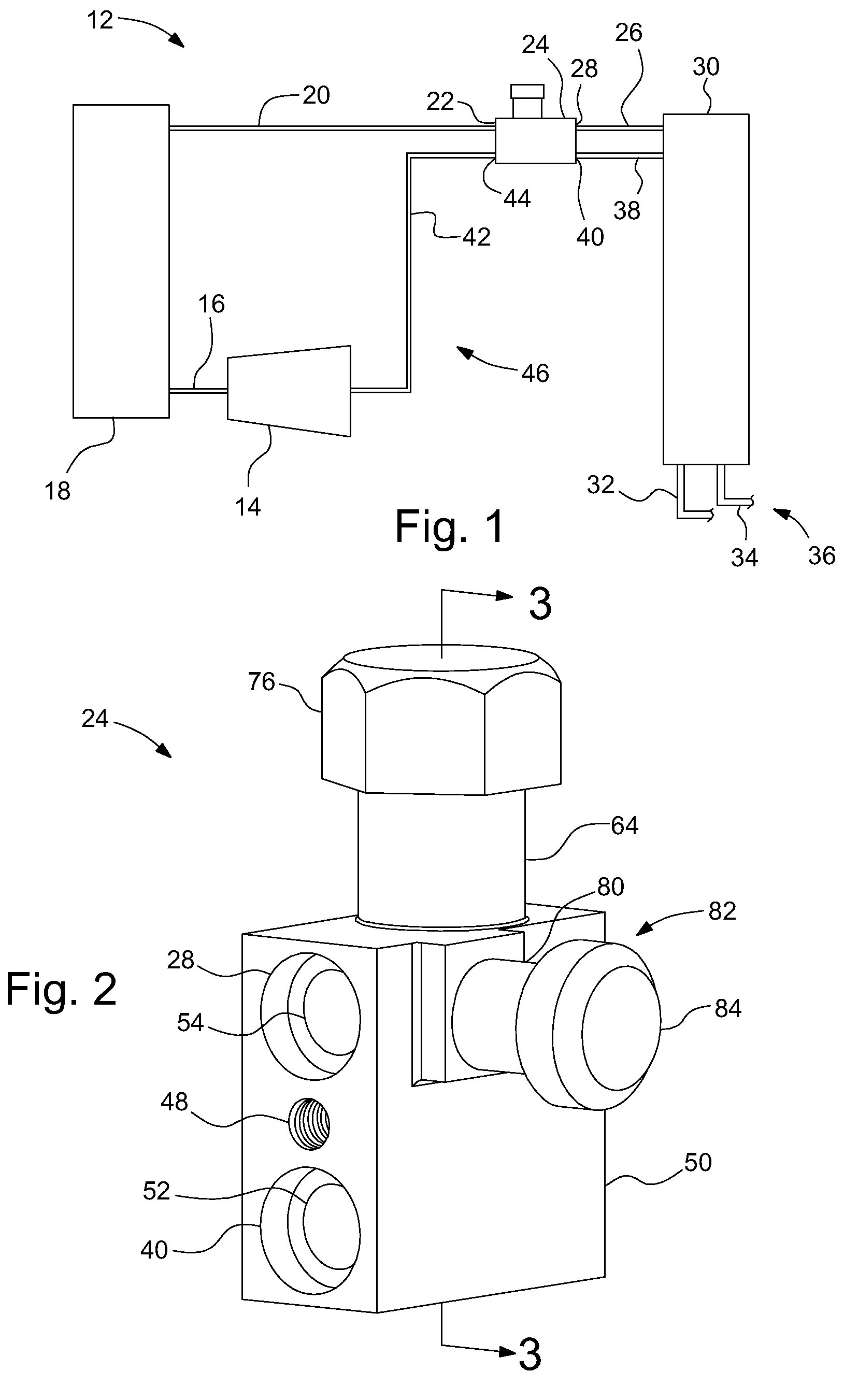
FIGS. 2 and 3 illustrate the refrigerant expansion assembly 24 shown in FIG. 1 in more detail. The refrigerant expansion assembly 24 has a main body 50 that defines a pair of mounting bores 48 for mounting the assembly 24.

The main body 50 also defines the orifice inlet port 22, the orifice outlet port 28, the return inlet port 40 and the return outlet port 44. The return inlet port 40 and the return outlet port 44 are coaxially aligned with each other and are connected by a refrigerant return channel 52 extending through the main body 50. The orifice inlet port 22 and the orifice outlet port 28 are coaxially aligned with each other and extend parallel to the return inlet and outlet ports 40, 44, but do not connect with or have any interaction with the return inlet and outlet ports 40, 44 (as is the case with a thermal expansion valve that has an opening between the orifice ports and the return ports that is covered with a diaphragm that is used to affect the valve opening). The orif...

second embodiment

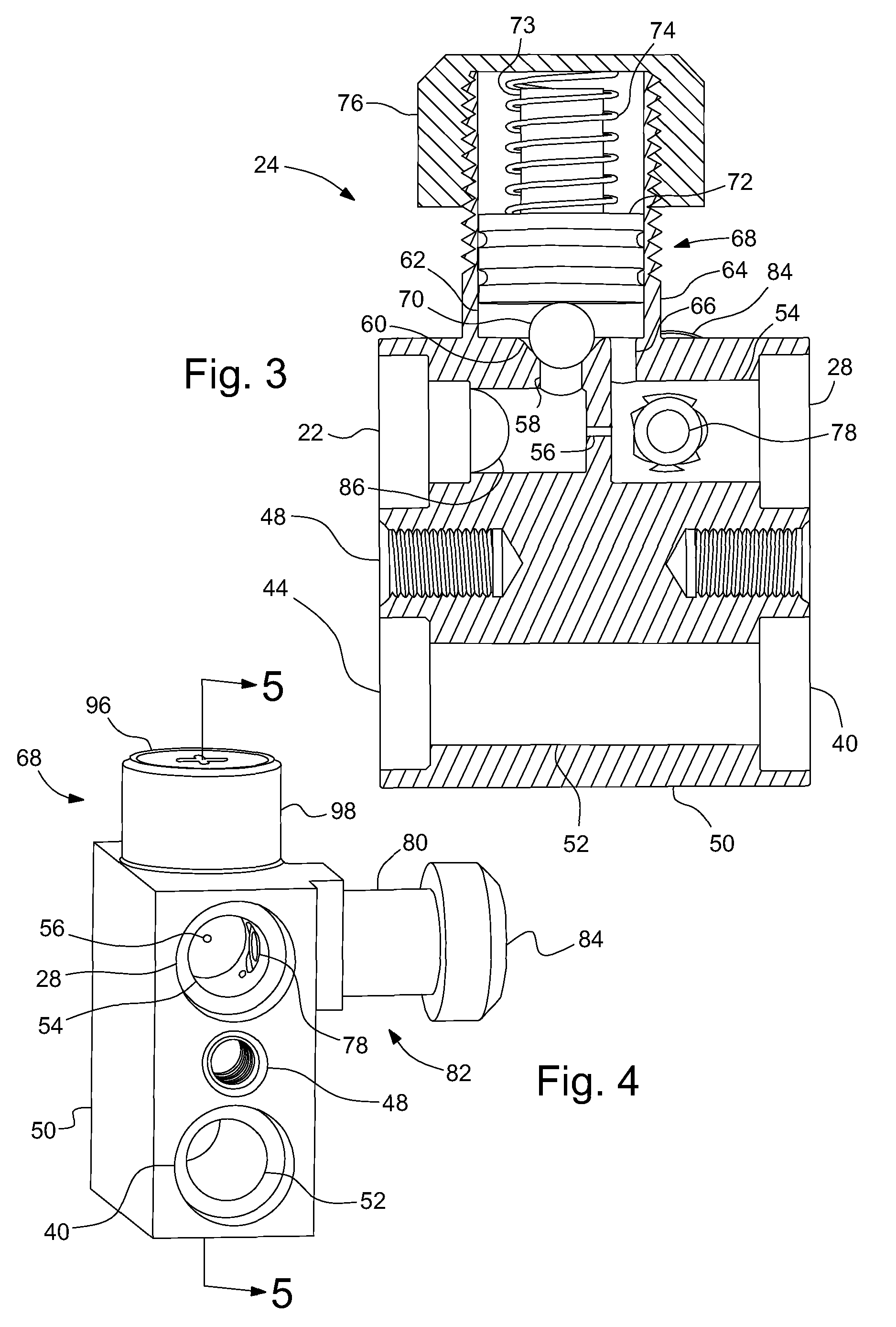
FIGS. 4-6 illustrate a Since this embodiment is similar to the first, similar element numbers will be used for similar elements, and the detailed description thereof will be omitted. In this embodiment, the orifice bypass valve 68 is modified to provide a different means of biasing the check ball 70 onto the valve seat 60.

A plate spring 90 is mounted in the bypass valve flange 98 and secured in place by screwing the spring retention nut 96 into the bypass valve flange 98. The plate spring 90 includes a ball contact tab 94 that is aligned and in contact with the check ball 70 and a flexing member that supports the ball contact tab 94 in a cantilevered fashion. The plate spring 90 is more compact than a coil spring and can have its spring rate changed relatively easily by changing a thickness and / or width of the flexing member 92. Also, the more compact plate spring 90 allows for the spring retention nut 96 to be screwed inside of the bypass valve flange 98, thus providing for a more...


PUM


Abstract

A refrigerant expansion assembly, and method of operation, for use in a vehicle air conditioning system is disclosed. The assembly has a main body including an orifice inlet port, an orifice outlet port, an orifice channel extending between the orifice inlet and outlet ports and including a fixed orifice, an upstream bypass channel extending from the orifice channel between the orifice inlet port and the fixed orifice and including a valve seat, and a downstream bypass channel extending from the orifice channel between the fixed orifice and the orifice outlet port. A bypass valve flange extends from the main body, forming a bypass chamber connected to the upstream bypass channel and the downstream bypass channel, with the ball valve seat adjacent to the bypass chamber. A check ball mounts in the bypass chamber adjacent to the valve seat, and a spring biases the check ball into the valve seat.

Description

BACKGROUND OF INVENTIONThe present invention relates generally to vehicle air conditioning systems and more particularly to refrigerant expansion devices for vehicle air conditioning systems that employ higher pressure, non-conventional refrigerants.New regulations for refrigerants used in vehicle air conditioning systems are causing some vehicle air conditioning systems to employ refrigerants that operate at much higher pressures than conventional refrigerants used in vehicles. With these much higher pressures, the typical expansion devices used with the conventional refrigerants are not adequate. Accordingly, some have modified thermal expansion valves to operate at the higher pressures of the new refrigerants, but drawbacks exist with the diaphragm located in the thermal expansion valve between the inflow refrigerant stream and the outflow refrigerant stream, and with a tube used for a temperature sensor, which is easily broken during assembly. Others have attempted to provide or...

Claims


Application Information

Patent Timeline
Patent Type & Authority Patents(United States)
IPC IPC(8): F25B41/04
CPCF16K15/046F25B41/067F25B49/005F25B2400/0411F25B2500/18
Inventor LU, JANEUSTICE, HARRY E.STANKE, EDWIN J.
Owner GM GLOBAL TECH OPERATIONS LLC
Why Eureka
Try Eureka