Variable Refrigerant Expansion Device with Pressure Relief

a technology of expansion device and refrigerant, which is applied in the field of vehicle air conditioning systems, can solve the problems of insufficient expansion device used with conventional refrigerants, easy to break, and complex orifice tube assembly, etc., and achieves the effects of improving refrigerant flow, simple, inexpensive and reliable assembly, and simple, inexpensive and reliable design

Inactive Publication Date: 2009-11-26
GM GLOBAL TECH OPERATIONS LLC
View PDF11 Cites 3 Cited by
  • Summary
  • Abstract
  • Description
  • Claims
  • Application Information

AI Technical Summary

Benefits of technology

[0006]An advantage of an embodiment is that the refrigerant expansion assembly has both an orifice bypass valve to relieve high pressure upstream of the orifice, and a pressure relief valve that will release refrigerant pressure when the pressure is high enough that damage to the evaporator is possible—all in a relatively simple, inexpensive and reliable assembly. The pressure relief is particularly useful when employing refrigerants that operate at a higher pressure than conventional vehicle refrigerants, such as, for example, carbon dioxide refrigerant systems. The orifice bypass valve is a simple, inexpensive and reliable design for achieving the desired pressure relief.
[0007]An advantage of an embodiment is that the orifice assembly is variable, allowing for improved refrigerant flow by allowing for variable refrigerant flow through the orifice.
[0008]An advantage of an embodiment is that a refrigerant filter member is removable for service, thus reducing costs associated with assembly and servicing of a clogged filter.
[0009]An advantage of an embodiment is that the refrigerant expansion assembly includes a compact design with four parallel port connections, thus allowing for easier packaging in the vehicle.

Problems solved by technology

With these much higher pressures, the typical expansion devices used with the conventional refrigerants are not adequate.
Accordingly, some have modified thermal expansion valves to operate at the higher pressures of the new refrigerants, but drawbacks exist with the diaphragm located in the thermal expansion valve between the inflow refrigerant stream and the outflow refrigerant stream and with a tube used for a temperature sensor, which is easily broken during assembly.
But this orifice tube assembly is overly complex and expensive to fabricate and assemble.

Method used


Image

  • Variable Refrigerant Expansion Device with Pressure Relief
  • Variable Refrigerant Expansion Device with Pressure Relief
  • Variable Refrigerant Expansion Device with Pressure Relief

Examples


Embodiment Construction

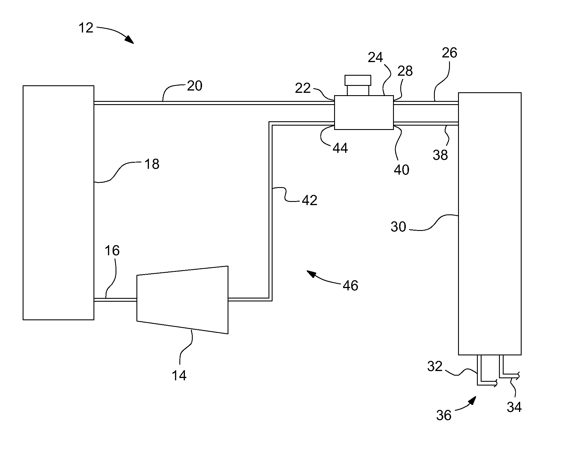
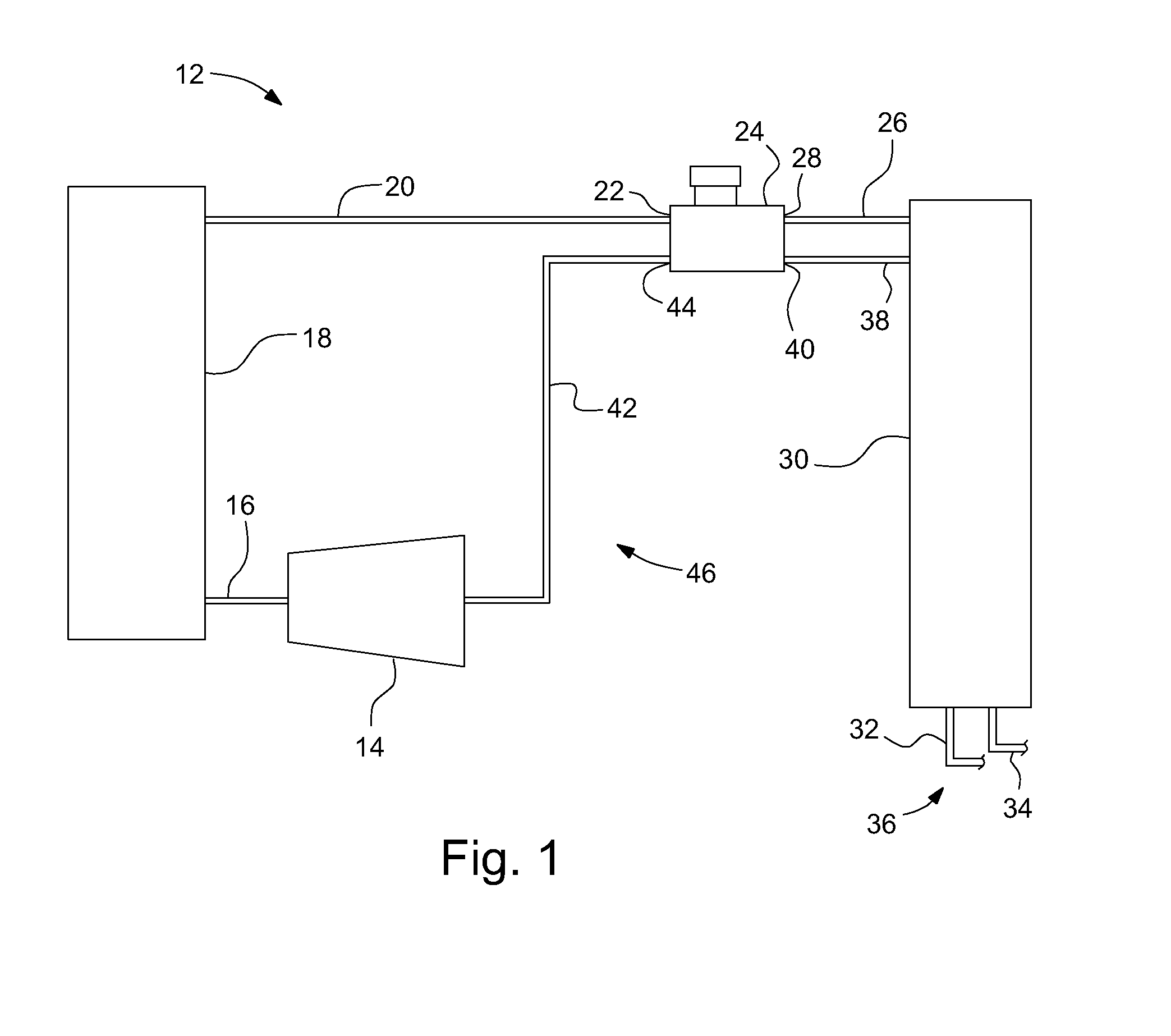
[0015]FIG. 1 illustrates a portion of a vehicle air conditioning system 12 for use with alternative refrigerants operating at a much higher pressure than conventional refrigerants used in automotive vehicles. The high pressure refrigerant may be, for example, carbon dioxide refrigerant rather than conventional automotive refrigerants such as R134a or Freon. The air conditioning system 12 includes a refrigerant compressor 14 that compresses a refrigerant before sending it through a refrigerant line 16 to a condenser 18, where heat energy is removed from the refrigerant. Another refrigerant line 20 directs the refrigerant from the condenser 18 to an orifice inlet port 22 of a refrigerant expansion assembly 24. Still another refrigerant line 26 connects between an orifice outlet port 28 of the expansion assembly 24 and an evaporator 30.

[0016]The evaporator 30 is also sometimes referred to as a chiller and includes a secondary loop outlet line 32 and a secondary loop inlet line 34, whic...


PUM


Abstract

A refrigerant expansion assembly, and method of operation, for use in a vehicle air conditioning system is disclosed. An orifice channel connects an orifice inlet port to an orifice outlet port and includes a valve seat. A variable orifice assembly is mounted in the orifice channel and includes a fixed orifice passage extending axially through a variable orifice body having a sealing flange that can seal against a valve seat via an orifice spring. An orifice bypass valve includes a check ball biased against a ball seat by a bypass spring and selectively allows some of the refrigerant to bypass the variable orifice assembly. The refrigerant expansion assembly may also include a burst disk downstream of the variable orifice assembly.

Description

BACKGROUND OF INVENTION[0001]The present invention relates generally to vehicle air conditioning systems and more particularly to variable refrigerant expansion devices for vehicle air conditioning systems that employ higher pressure, non-conventional refrigerants.[0002]New regulations for refrigerants used in vehicle air conditioning systems are causing some vehicle air conditioning systems to employ refrigerants that operate at much higher pressures than conventional refrigerants used in vehicles. With these much higher pressures, the typical expansion devices used with the conventional refrigerants are not adequate. Accordingly, some have modified thermal expansion valves to operate at the higher pressures of the new refrigerants, but drawbacks exist with the diaphragm located in the thermal expansion valve between the inflow refrigerant stream and the outflow refrigerant stream and with a tube used for a temperature sensor, which is easily broken during assembly. Others have att...

Claims


Application Information

Patent Timeline
Patent Type & Authority Applications(United States)
IPC IPC(8): F25B41/04
CPCF16K15/044F25B41/062F25B2500/18F25B2400/0411F25B49/005F25B41/325F25B41/32
Inventor LU, JANEUSTICE, HARRY E.STANKE, EDWIN J.
Owner GM GLOBAL TECH OPERATIONS LLC
Why Eureka
Try Eureka