Overvoltage protection device with dual contact surface thermal disconnector

a protection device and thermal disconnector technology, applied in the direction of emergency protective arrangements for limiting excess voltage/current, spark gap details, arrangements responsive to excess voltage, etc., can solve the problems of presenting risks to users, serious damage to the installation, and use of certain toxic materials, so as to improve the mechanical strength of the disconnection. , the effect of simple, inexpensive and reliable design

Inactive Publication Date: 2009-07-07
ABB FRANCE SAS
View PDF8 Cites 15 Cited by
  • Summary
  • Abstract
  • Description
  • Claims
  • Application Information

AI Technical Summary

Benefits of technology

[0015]The features of the present invention address the various disadvantages listed above and provide a device for protecting an electrical installation from overvoltages, with thermal disconnection means having improved mechanical strength.
[0017]Another feature of the present invention is to provide an overvoltage protection device with a particularly simple, inexpensive and reliable design.
[0018]Finally, another feature of the present invention is to provide a method for producing an overvoltage protection device making it possible to improve the mechanical strength of the disconnection means of the device.
[0019]The features of the present invention are achieved by a device for protecting an electrical installation from overvoltages, including at least one protection component intended to be connected to the electrical installation, as well as disconnection means capable of ensuring the electrical disconnection of the protection component from the installation, the disconnection means being capable of being moved from a closed configuration in which the protection component is connected to the electrical installation to an open configuration in which the protection component is disconnected from the electrical installation, wherein the device comprises at least one first fuse element and one second fuse element capable of holding the disconnection means in the closed configuration, and wherein the disconnection means comprise at least one first contact surface and one second contact surface substantially intersecting with one another and to which the first and second fuse elements respectively adhere when the disconnection means are in the closed configuration, to distribute the stresses exerted on the fuse elements and reinforce the mechanical strength of the disconnection means.
[0020]The features of the present invention are also achieved by means of a method for producing a device for protecting an electrical installation from overvoltages including at least one protection component intended to be connected to an electrical installation, as well as disconnection means capable of ensuring the electrical disconnection of the protection component from the installation, the disconnection means being capable of being moved from a closed configuration in which the protection component is connected to the electrical installation to an open configuration in which the protection component is disconnected from the electrical installation, wherein the method comprises a step of producing the disconnection means in which the disconnection means are given at least one first contact surface and one second contact surface substantially intersecting with one another, as well as an assembly step in which at least one first fuse element and one second fuse element are mounted in the device so that the fuse elements can hold the disconnection means in the closed configuration, and so that the first and second fuse elements respectively adhere to the first and second contact surfaces when the disconnection means are in the closed configuration, to distribute the stresses exerted on the fuse elements and reinforce the mechanical strength of the disconnection means.

Problems solved by technology

In the event of a failure, protection components may be subject to significant heating that can cause serious damage to the installation and present risks to the user, for example, by starting a fire.
Thus, when excessive heating of the protection component causes the solder to melt, the mobile conductive element separates from the power supply terminal of the protection component, thus isolating the power supply terminal from the installation to be protected.
Normally, the alloys used for this purpose contain lead and often other toxic materials such as cadmium.
However, health regulations will soon prohibit the use of certain toxic materials, in particular lead, as a material constituting electrical and electronic products.
While such alloys are known, such as, for example, certain tin-bismuth alloys, it is impossible to replace fuse elements in the same state in the existing overvoltage protection devices because the known lead-free alloys do not have the same mechanical properties, and particularly do not have the same stress resistance as the lead alloys.
In particular, this lower mechanical strength exposes the weld joint to premature rupture capable of occurring under the effect of the electrodynamic stresses exerted on the conductive elements of the protection device when traversed by a discharge current corresponding to the limitation of an overvoltage in the context of its normal operation.
Two major difficulties are encountered in the replacement of lead fuse elements with lead-free fuse elements.
The first major difficulty is maintaining a low enough melting point to ensure the safety of operation, i.e., a fast enough activation of the thermal disconnection means; and the second major difficulty is to have adequate mechanical strength in the connection produced by the fuse element, in particular so as not to disturb the normal operation of the device by an inappropriate disconnection during the conduction of a discharge current.

Method used


Image

  • Overvoltage protection device with dual contact surface thermal disconnector
  • Overvoltage protection device with dual contact surface thermal disconnector
  • Overvoltage protection device with dual contact surface thermal disconnector

Examples


Embodiment Construction

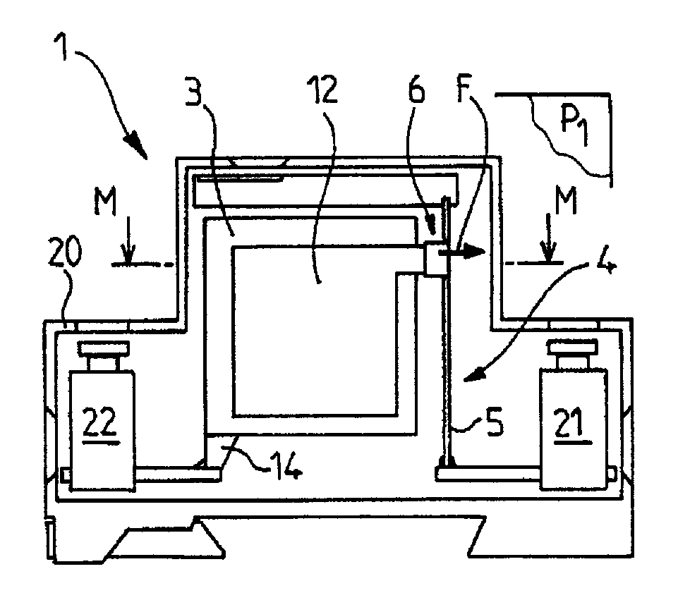
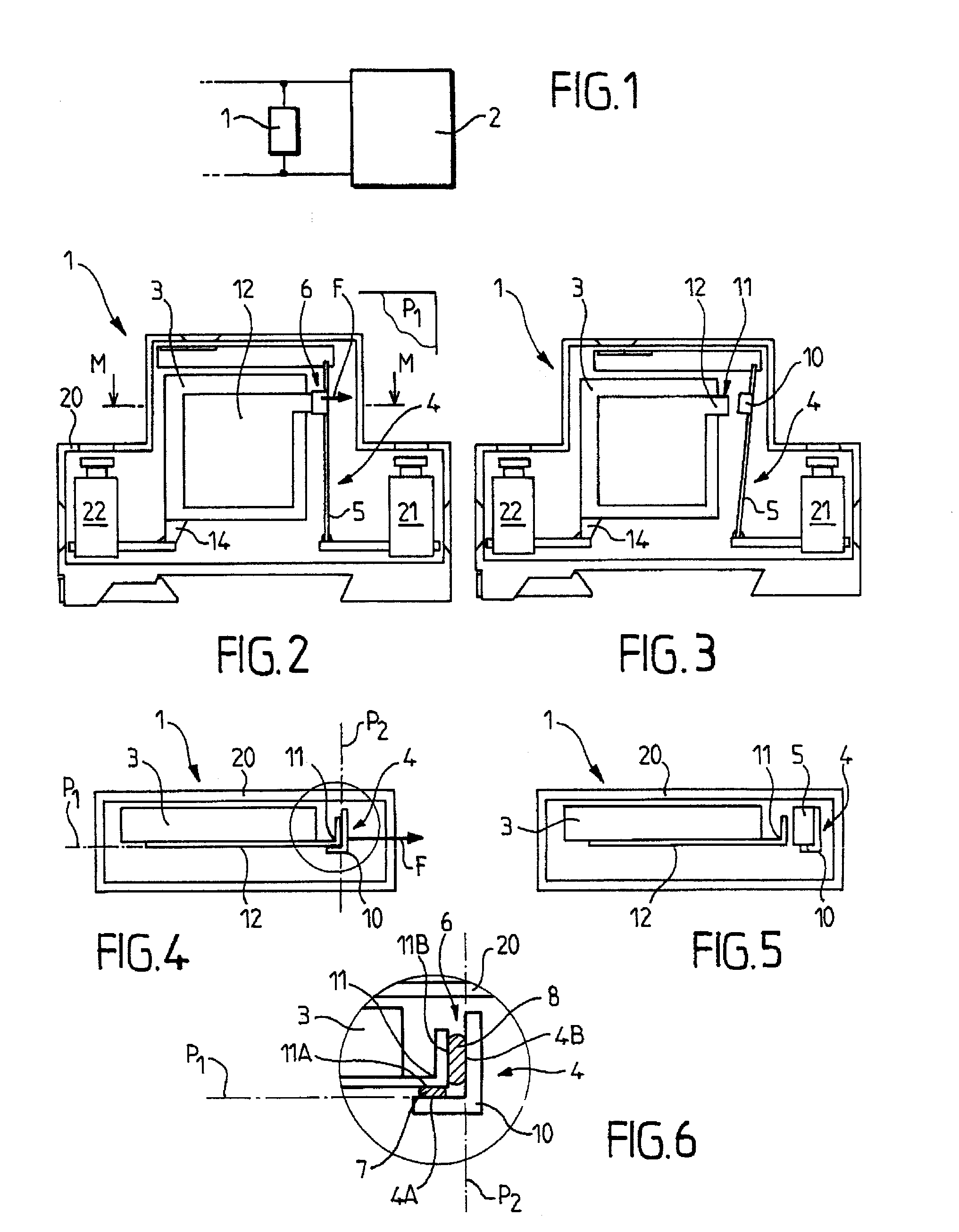
[0029]The device 1 for protecting an electrical installation 2 from overvoltages, according to the present invention, is intended to be shunt-connected (or connected “in parallel”) to the electrical installation 2 in order to protect the electrical installation from overvoltages, as shown in FIG. 1.

[0030]For purposes of the present disclosure, the term “electrical installation” refers to any type of electrically powered apparatus or network capable of undergoing voltage disturbances, in particular transient overvoltages caused by lightning.

[0031]The protection device 1 can advantageously constitute a lightning arrestor.

[0032]The overvoltage protection device 1 according to the present invention is advantageously intended to be placed between a phase of the installation to be protected 2 and the ground. It is also possible to envisage, without going beyond the scope of the present invention, that the device 1, instead of being shunt-connected between a phase and the ground, is connec...


PUM


Abstract

A device (1) for protecting an electrical installation (2) from overvoltages, including at least one protection component (3), and disconnection element (4) capable of ensuring the electrical disconnection of the protection component from the installation by moving from a closed configuration to an open configuration, wherein the device (1) has at least one first fuse element (7) and one second fuse element (8) capable of holding the disconnection element (4) in the closed configuration, and wherein the disconnection element (4) includes at least one first contact surface (4A) and one second contact surface (4B) substantially intersecting with one another and to which the first and second fuse elements respectively adhere when the disconnection element (4) are in the closed configuration, to distribute the stresses exerted on the fuse elements and reinforce the mechanical strength of the disconnection element.

Description

PRIORITY CLAIM[0001]This patent application claims priority to French Patent application No. 06 01677, filed Feb. 24, 2006, the disclosure of which is incorporated herein by reference in its entirety.FIELD OF THE INVENTION[0002]The present invention relates to devices for protecting electrical installations and equipment from electrical overvoltages, in particular transient overvoltages, especially caused by lightning.[0003]The present invention relates more specifically to devices for protecting an electrical installation from overvoltages.[0004]The present invention also relates to a method for producing a device for protecting an electrical installation from overvoltages.BACKGROUND OF THE INVENTION[0005]The use of protection devices capable of protecting electrical or electronic apparatuses from overvoltages, which may result, for example, from lightning, is known.[0006]These protection devices generally comprise one or more overvoltage protection components, such as, for example...

Claims


Application Information

Patent Timeline
Patent Type & Authority Patents(United States)
IPC IPC(8): H02H1/00
CPCH01C7/126H01H37/764H01T1/14H01H2037/768H01H2037/763
Inventor LAGNOUX, ALAIN RENE ROBERT
Owner ABB FRANCE SAS
Why Eureka
Try Eureka