Refrigerant Expansion Assembly with Pressure Relief
a technology of expansion assembly and refrigerant, which is applied in the field of refrigerant expansion devices, can solve the problems of overly complex and expensive fabrication and assembly of orifice tube assemblies, insufficient typical expansion devices used with conventional refrigerants, and easy to break, so as to reduce costs, simple, inexpensive and reliable assembly, the effect of simple, inexpensive and reliable design
- Summary
- Abstract
- Description
- Claims
- Application Information
AI Technical Summary
Benefits of technology
Problems solved by technology
Method used
Image
Examples
first embodiment
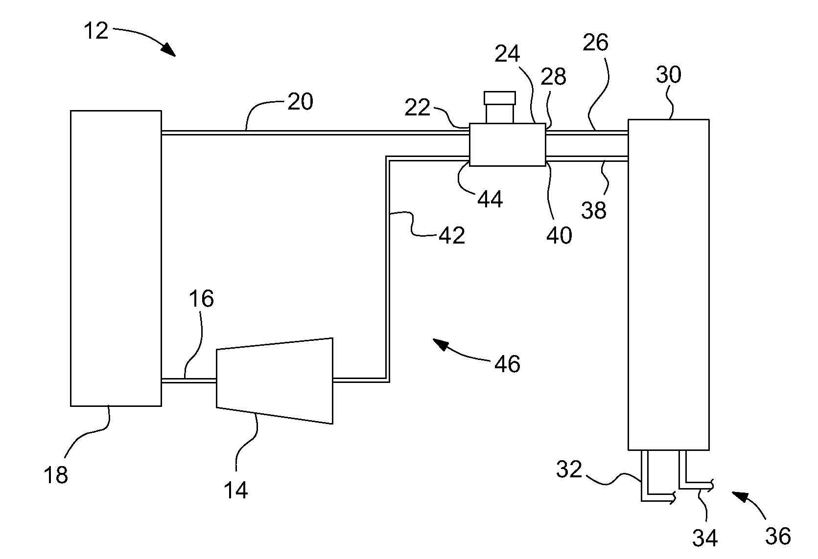
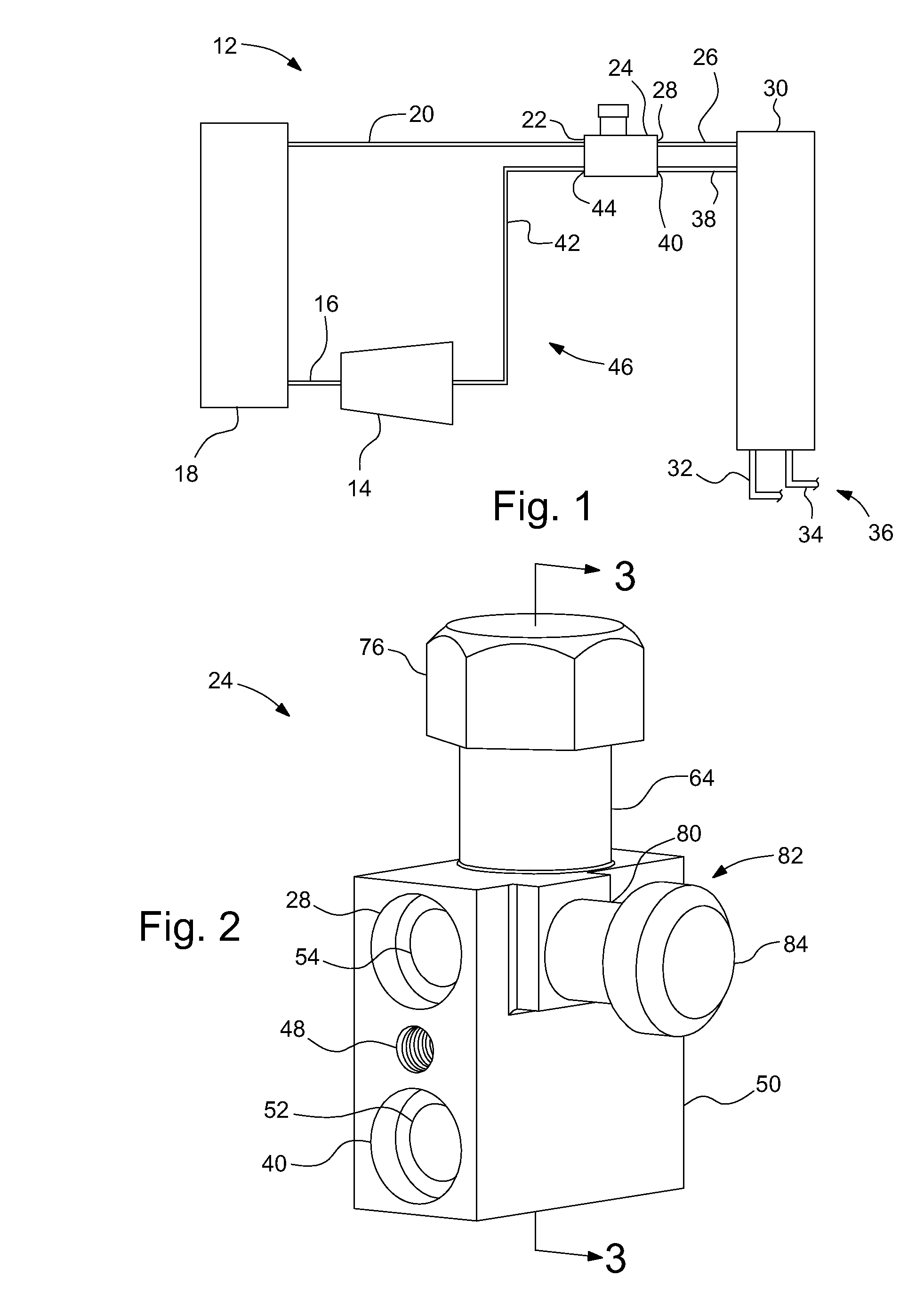
[0017]FIGS. 2 and 3 illustrate the refrigerant expansion assembly 24 shown in FIG. 1 in more detail. The refrigerant expansion assembly 24 has a main body 50 that defines a pair of mounting bores 48 for mounting the assembly 24.
[0018]The main body 50 also defines the orifice inlet port 22, the orifice outlet port 28, the return inlet port 40 and the return outlet port 44. The return inlet port 40 and the return outlet port 44 are coaxially aligned with each other and are connected by a refrigerant return channel 52 extending through the main body 50. The orifice inlet port 22 and the orifice outlet port 28 are coaxially aligned with each other and extend parallel to the return inlet and outlet ports 40, 44, but do not connect with or have any interaction with the return inlet and outlet ports 40, 44 (as is the case with a thermal expansion valve that has an opening between the orifice ports and the return ports that is covered with a diaphragm that is used to affect the valve openin...
second embodiment
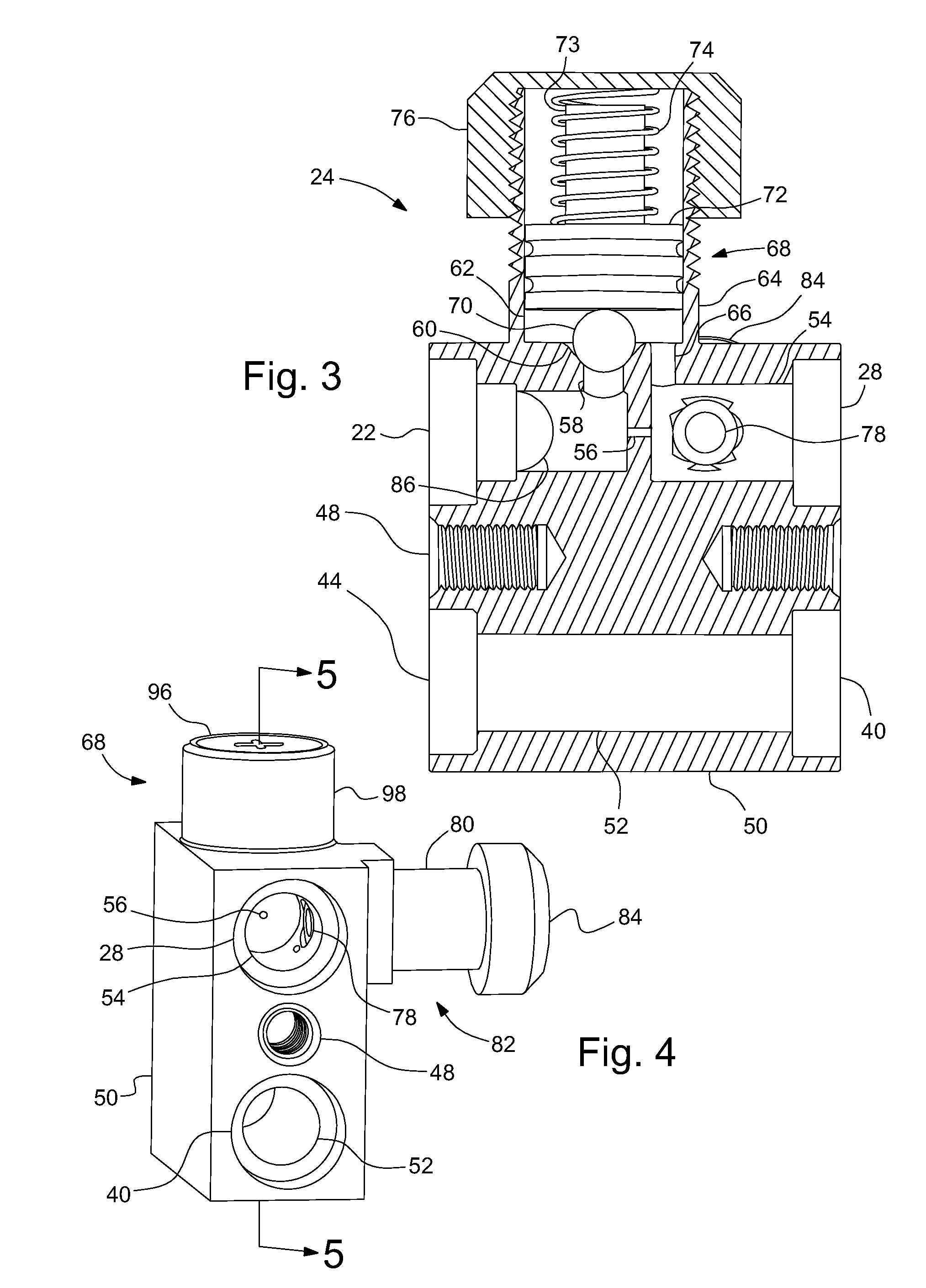
[0026]FIGS. 4-6 illustrate a Since this embodiment is similar to the first, similar element numbers will be used for similar elements, and the detailed description thereof will be omitted. In this embodiment, the orifice bypass valve 68 is modified to provide a different means of biasing the check ball 70 onto the valve seat 60.
[0027]A plate spring 90 is mounted in the bypass valve flange 98 and secured in place by screwing the spring retention nut 96 into the bypass valve flange 98. The plate spring 90 includes a ball contact tab 94 that is aligned and in contact with the check ball 70 and a flexing member that supports the ball contact tab 94 in a cantilevered fashion. The plate spring 90 is more compact than a coil spring and can have its spring rate changed relatively easily by changing a thickness and / or width of the flexing member 92. Also, the more compact plate spring 90 allows for the spring retention nut 96 to be screwed inside of the bypass valve flange 98, thus providin...
PUM
 Abstract
Description
Claims
Application Information
 - R&D
- Intellectual Property
- Life Sciences
- Materials
- Tech Scout
- Unparalleled Data Quality
- Higher Quality Content
- 60% Fewer Hallucinations
Browse by: Latest US Patents, China's latest patents, Technical Efficacy Thesaurus, Application Domain, Technology Topic, Popular Technical Reports.
© 2025 PatSnap. All rights reserved.Legal|Privacy policy|Modern Slavery Act Transparency Statement|Sitemap|About US| Contact US: help@patsnap.com


