Biometrics-based identification method and apparatus

a biometric and identification method technology, applied in the field of methods of identification, can solve the problems of inability to detect liveliness, and inability to fool identification apparatuses, etc., to achieve simple hardware and software, small distinctive power, and simple structure

Active Publication Date: 2011-04-12
KONINK PHILIPS ELECTRONICS NV
View PDF16 Cites 0 Cited by
  • Summary
  • Abstract
  • Description
  • Claims
  • Application Information

AI Technical Summary

Benefits of technology

[0010]Another advantage of the invention relates to the following aspects. In principle, it is possible to carry out identification based on an inner structure of a body member only. However, such identification is relatively unreliable for the following reasons. The inner structure of a body member, such as, for example, a blood-vessel pattern, generally has a relatively modest distinctive power. That is, it is difficult to uniquely distinguish a blood-vessel pattern of an individual from respective blood-vessel patterns of many other individuals. Consequently, it requires relatively complicated hardware or software, or both, in order to guarantee that a measured blood-vessel pattern can match with a single reference blood-vessel pattern only. It may even prove to be impossible to achieve the aforementioned.
[0011]In accordance with the invention, a surface and an inner structure are respectively measured and compared with reference results. The surface structure, such as, for example, a fingerprint has relatively great distinctive power. This distinctive power can compensate for a modest distinctive power of the inner structure, such as, for example, a blood-vessel pattern. The invention does not require that a measured blood-vessel pattern matches with a single reference blood-vessel pattern only. Consequently, reliable identification and authentication can be achieved with relatively simple hardware and software. For those reasons, the invention allows cost-efficient implementations.
[0012]These and other aspects of the invention will be described in greater detail hereinafter with reference to drawings.

Problems solved by technology

However, an identification apparatus with such liveliness detection remains vulnerable.
However, an identification apparatus will still be relatively sensitive to fraud even if one or more of the aforementioned techniques are applied.
Consequently, an identification apparatus can still be relatively easily fooled despite the aforementioned techniques.

Method used


Image

  • Biometrics-based identification method and apparatus
  • Biometrics-based identification method and apparatus
  • Biometrics-based identification method and apparatus

Examples


Embodiment Construction

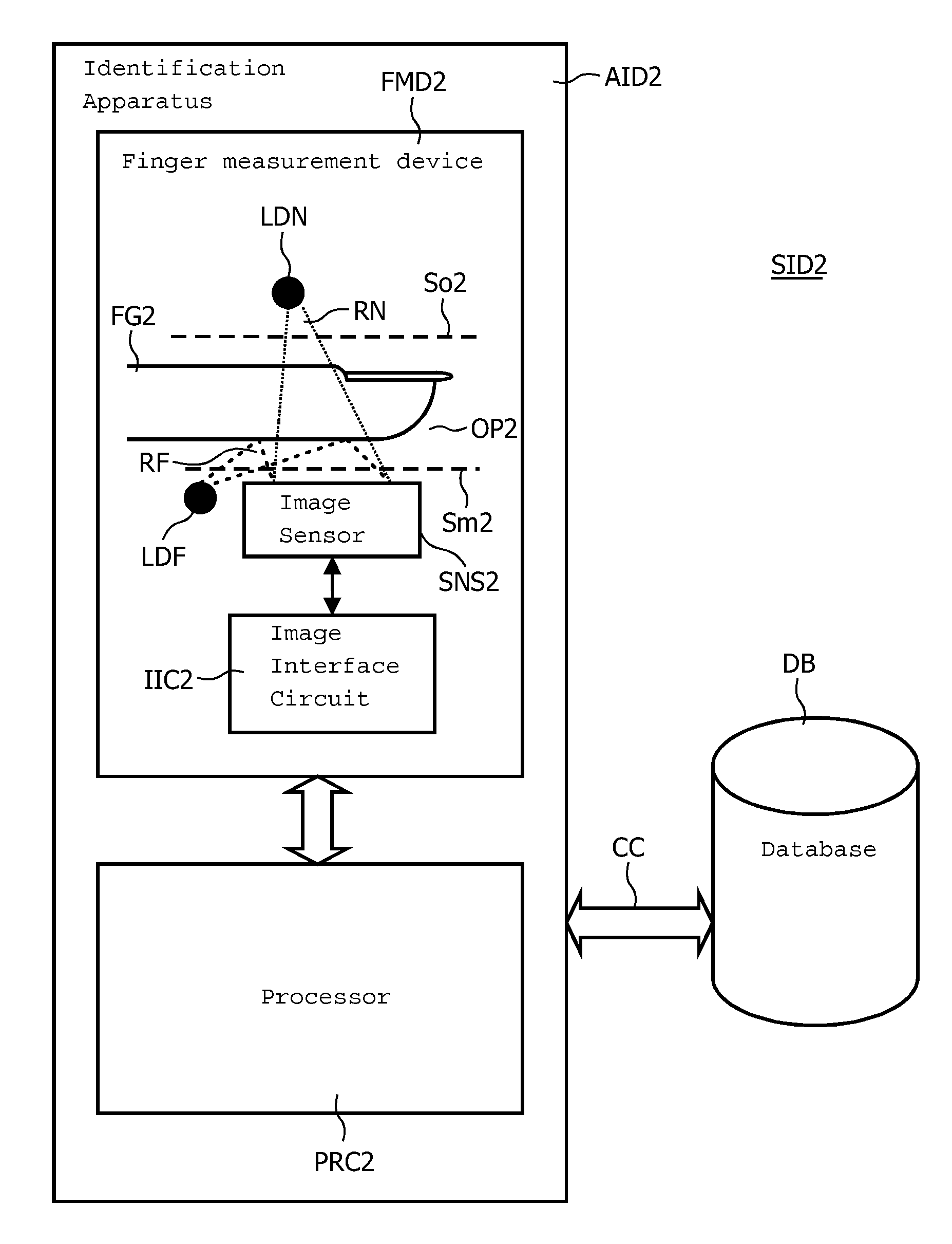
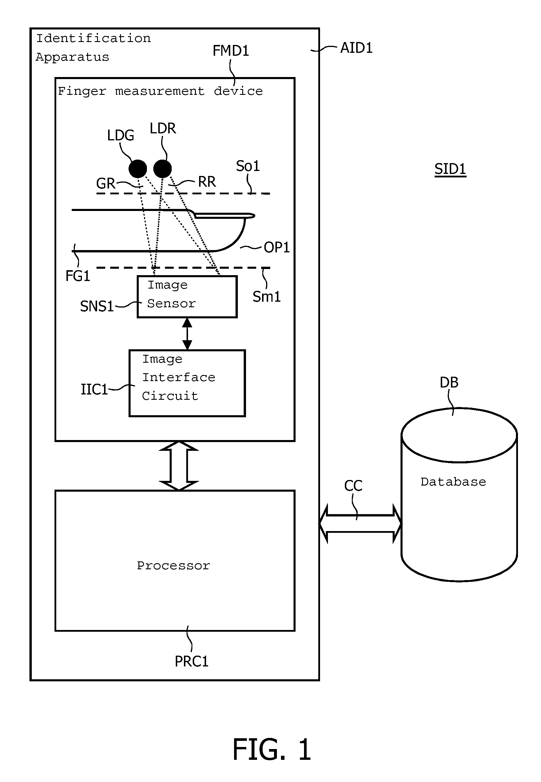
[0018]FIG. 1 illustrates an identification system SID1 which comprises an identification apparatus AID1 and a database DB exchanging data via a communication channel CC. The identification apparatus AID1 itself comprises a finger measurement device FMD1 and a processor PRC1. The finger measurement device FMD1 comprises an opening OP1 for receiving a finger FG1, a red-light source LDR, a green-light source LDG, an image sensor SNS1, and an image interface circuit IIC1. The image sensor SNS1 is located on a measurement side Sm1 of the opening OP1. The red-light source LDR and the green-light source LDG are located on an opposite side So1 of the opening OP1. The red-light source LDR and the green-light source LDG may be in the form of, for example, one or more light emitting diodes. The processor PRC1 may be in the form of, for example, a suitably programmed circuit. The processor PRC1 will typically comprise a program memory that comprises instructions, i.e. software, and one or more ...


PUM


Abstract

The invention relates to an identification method carried out as follows. A surface structure and an inner structure of a body member are measured (ST1-ST4, ST7) so as to obtain a surface-structure measurement result (FPM) and an inner-structure measurement result (BVPM), respectively. The surface-structure measurement result (FPM) is compared (ST5) with a surface-structure reference result (FPR) that distinguishes an individual from other individuals. The inner-structure measurement result (BVPM) is compared (ST8) with an inner-structure reference result (BVPR) that is associated with the same individual and that distinguishes the individual from other individuals. The body member may be, for example, a finger. In that case, the surface structure comprises a fingerprint and the inner structure comprises a blood-vessel pattern.

Description

FIELD OF THE INVENTION[0001]The invention relates to a method of identification that is based on biometric features. This method of identification may include, for example, a fingerprint measurement followed by a fingerprint comparison so as to identify a particular individual. Such a method can also be used to ascertain that a particular individual truly is who she or he claims to be. The latter is often referred to as authentication. Other aspects of the invention relate to an identification apparatus, an identification system and a computer-program product for an identification apparatus.DESCRIPTION OF PRIOR ART[0002]European patent application published under number EP 1 353 292 describes an optical biometric sensor apparatus for analyzing images of fingerprints. Live body members are detected by transmitting infrared light from an infrared light source to an image sensor. The infrared transmission characteristics of a live body member vary with the human heartbeat. Multiple ima...

Claims


Application Information

Patent Timeline
Patent Type & Authority Patents(United States)
IPC IPC(8): G05B19/00G06V40/13G06F21/32G06V40/14G06V40/40
CPCG06K9/00013G06K9/00899G06K9/0012G06K2009/00932G06V40/13G06V40/1394G06V40/40G06V40/14A61B5/117G06T1/00G06F18/00
Inventor HENDRIKS, ROBERT FRANS MARIARENSEN, WOUTER HARRY JACINTHAKKERMANS, ANTONIUS HERMANUS MARIA
Owner KONINK PHILIPS ELECTRONICS NV
Why Eureka
Try Eureka