Portable balloon tying device, station and caddy

a tying device and portable technology, applied in the field of portable tying devices, can solve the problems of difficulty in passing the end, fatigue of hands, especially fingers, and often required extra time to avoid

Active Publication Date: 2011-06-28
HERREN GERALD R
View PDF4 Cites 24 Cited by
  • Summary
  • Abstract
  • Description
  • Claims
  • Application Information

AI Technical Summary

Problems solved by technology

The loop is usually made around one or more fingers, which has disadvantages, among which are: 1. Difficulty of passing the end through the loop, because the material is generally kept very tight to prevent air or gas from escaping from the balloon; 2. Damage to the material w

Method used


Image

  • Portable balloon tying device, station and caddy
  • Portable balloon tying device, station and caddy
  • Portable balloon tying device, station and caddy

Examples


second embodiment

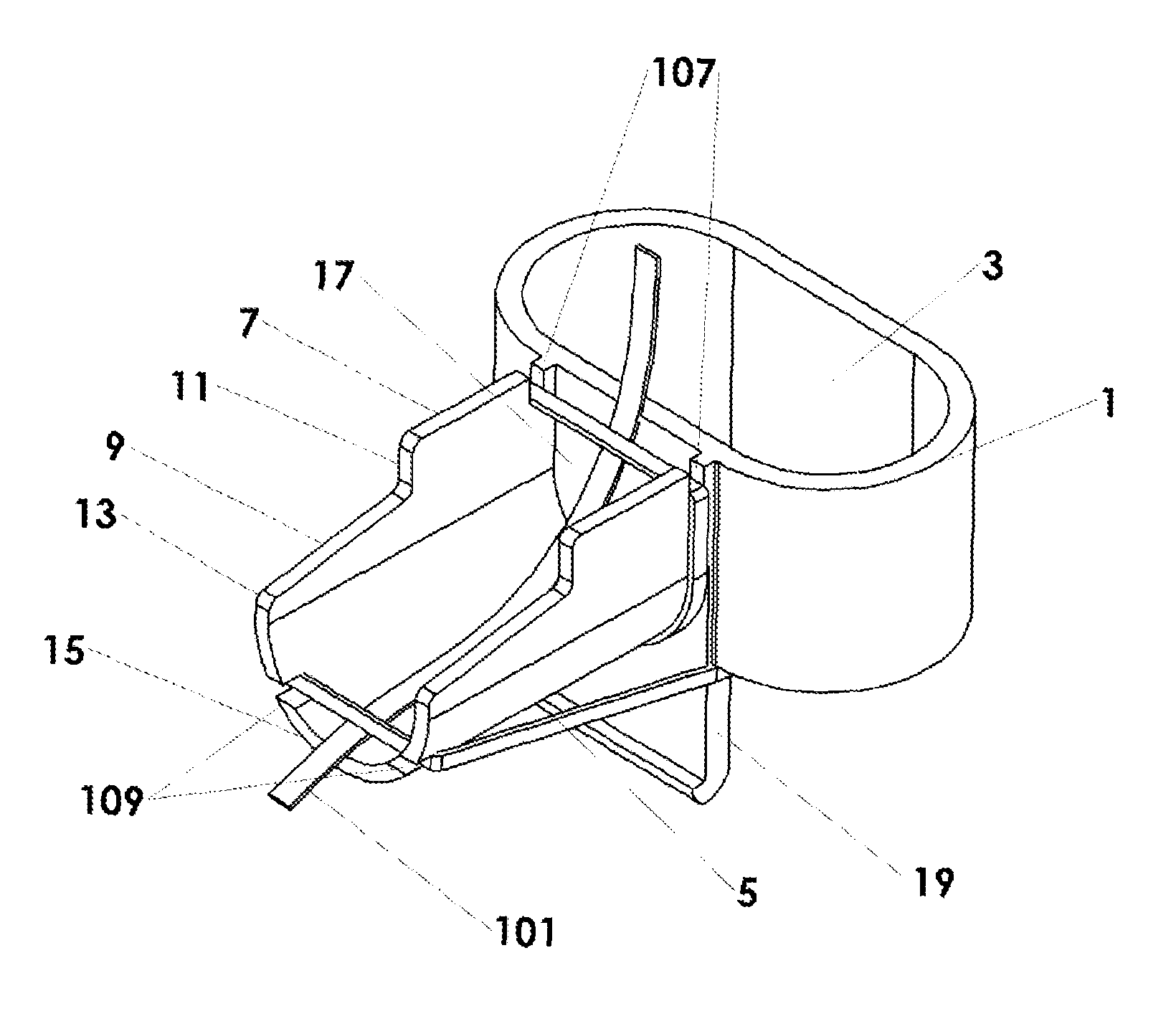
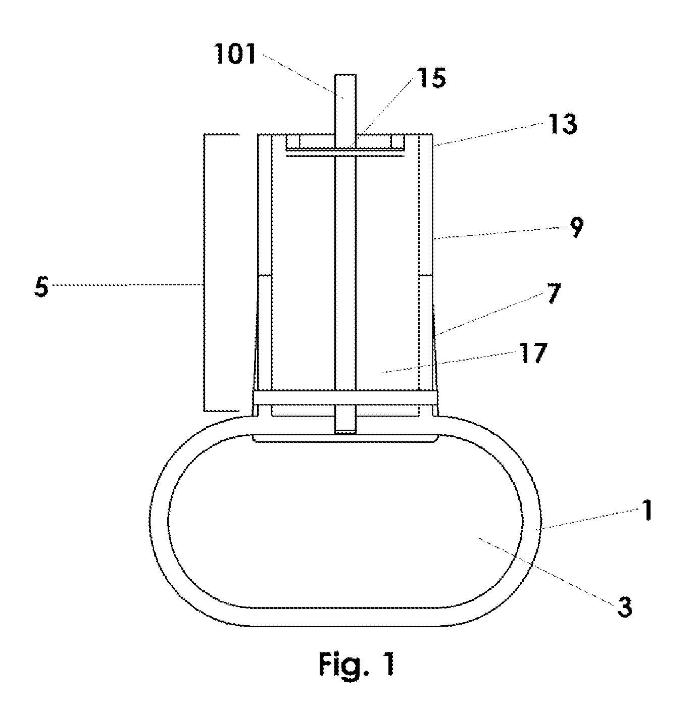
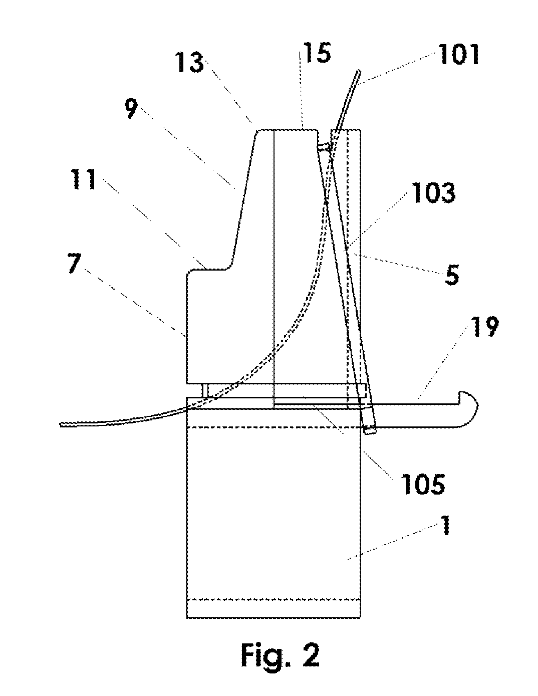
[0037]FIG. 9 is an isometric view of the invention preferably used for tying balloons to spooled ribbon 101. Instead of using bands to retain the ribbon, two pins are removably disposed in the recess 17 of the cantilever 5. A proximal pin 90 is removably disposed in the cantilever proximal region and a distal pin 92 is removably disposed in the cantilever distal region. Spooled ribbon 101 is fed beneath the pins and remains in the lower quadrant of the recess 17 to clear way for tying the knot in a balloon. Spooled ribbon can be continuously fed through the device thereby enabling multiple balloons to be integrated on the same length of ribbon for use in balloon arches.

third embodiment

[0038]FIG. 10 is an isometric view of the invention preferably used for tying balloons to pre-cut ribbons of any length, preferably between 2 and 6 feet. A distal ribbon guide 94 is removably disposed in the distal cantilever region, preferably by snapping the guide's rear lip projection under the distal pin 92 for a press fit. The proximal pin 90 is not used with pre-cut ribbon. A proximal ribbon guide 96 is disposed on the upper edge of the base 1. The center portion of the proximal ribbon guide has two mounting slots 98 that can be used to mount the device to a support structure. If the support structure blocks the center portion of the proximal ribbon guide 96 a side portion of the proximal ribbon guide 96 can be used to guide the pre-cut ribbon into the recess 17. Other tying operations are common to all embodiments.

[0039]FIG. 13 shows an embodiment of the invention in a tying station 112 that allows users to travel to parties and such for tying the balloons on-site. Station st...


PUM


Abstract

A balloon tying device has a base adapted for attaching to a support structure. A cantilever, supported by the base and protruding away from the support structure, is attached to the base. The cantilever has a U-shaped cross section and two ears defining generally parallel planes extending outwardly and terminating at the tip for retaining a loop of balloon material. Inside the U-shape of the cantilever is an axially oriented recess for passing ribbon and providing clearance for tucking the overhand knot. A brace tab extends downward from the lower edge of the base. A ribbon retainer is disposed on the device for integrating spooled or pre-cut ribbon into the balloon knot. The support structure can be human fingers, a station stanchion, a tank stand, or a caddy leg.

Description

CROSS-REFERENCE TO RELATED APPLICATIONS[0001]This application claims priority from U.S. Provisional Patent 60 / 890,478 filed Feb. 17, 2007. This application is also related to U.S. Pat. No. 5,568,950, issued Oct. 28, 1996.TECHNICAL FIELD[0002]This invention relates to devices that aid in tying knots and more particularly to portable devices with support structures to aid in hand-tying half-hitch knots, especially in balloons and the like. Spooled and pre-cut ribbon can be tied integral with the knot. A tying station, tank stand and caddy to support and transport the devices are also taught.BACKGROUND OF THE INVENTION[0003]Balloons with ribbons and the like are generally tied with a half-hitch knot. First, a loop is made in the balloon tail, passing the end over the standing part, then passing the end under the standing part and through the loop. See The World Book Dictionary, Clarence L. Barnhart and Robert K. Barnhart, editors, World Book, Inc., publisher, 1990, page 956, column 3. ...

Claims


Application Information

Patent Timeline
IPC IPC(8): D03J3/00
CPCA63H27/10A63H2027/105
Inventor HERREN, GERALD R.
Owner HERREN GERALD R
Why Eureka
Try Eureka