
Adjustable smooth bore nozzle
a smooth bore, adjustable technology, applied in the direction of diaphragm valves, engine diaphragms, mechanical equipment, etc., can solve the problems of bore nozzles, fixed diameter, limited flow rate range,
- Summary
- Abstract
- Description
- Claims
- Application Information
AI Technical Summary
Benefits of technology
Problems solved by technology
Method used
Image

Examples
first embodiment
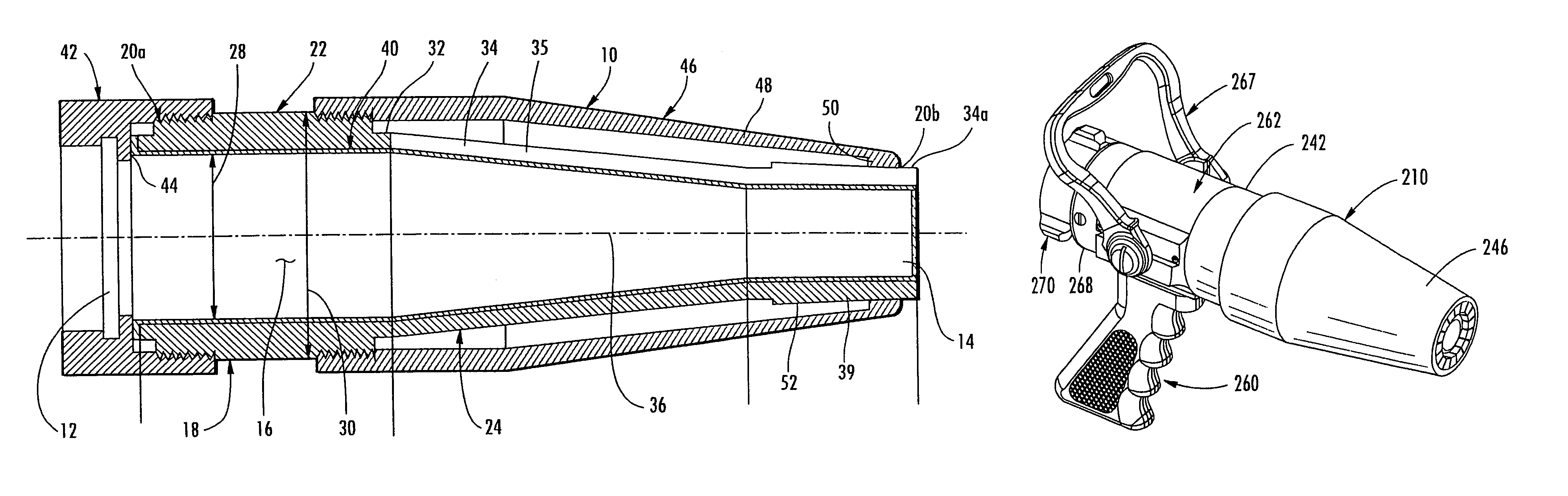
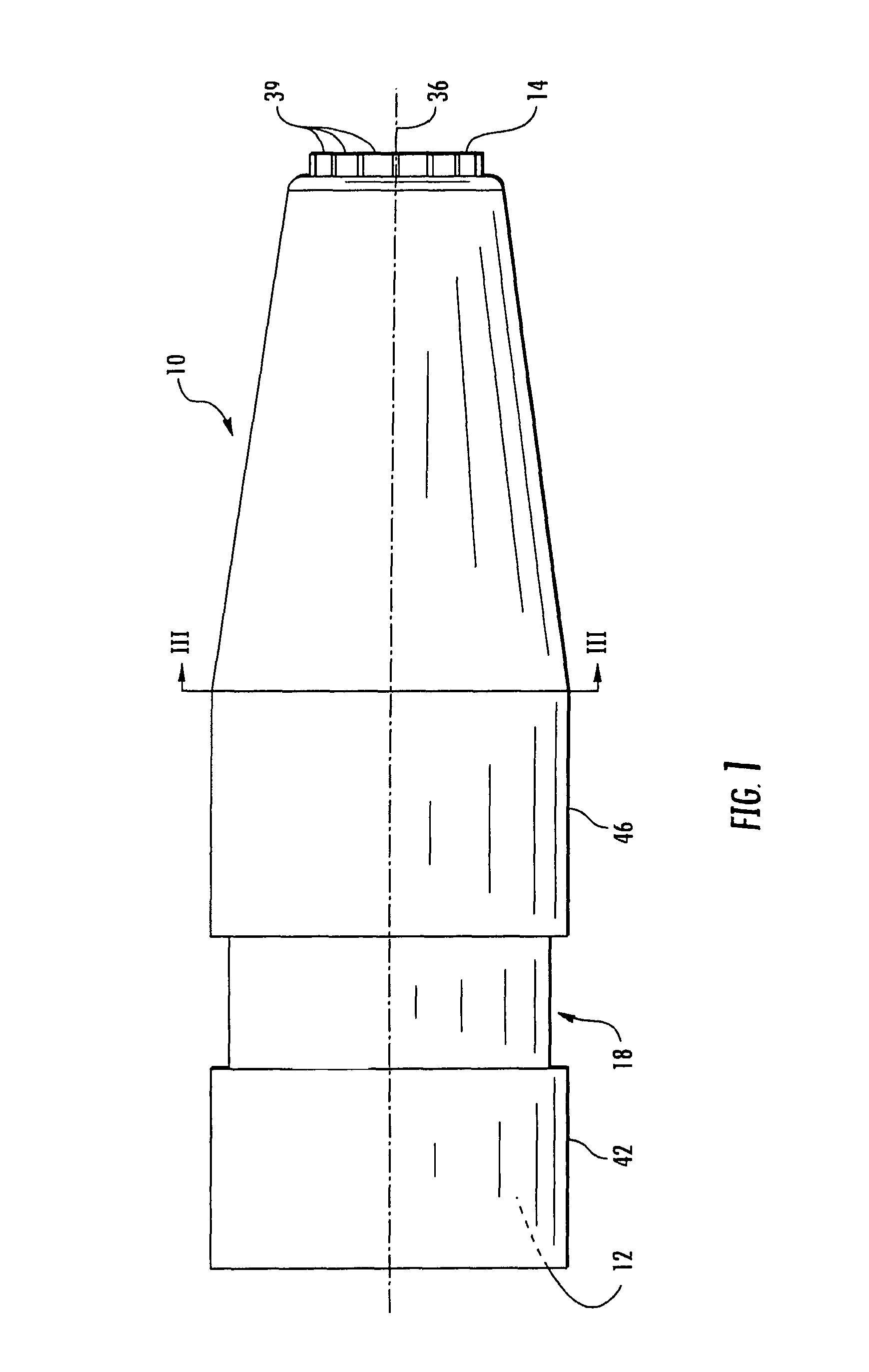
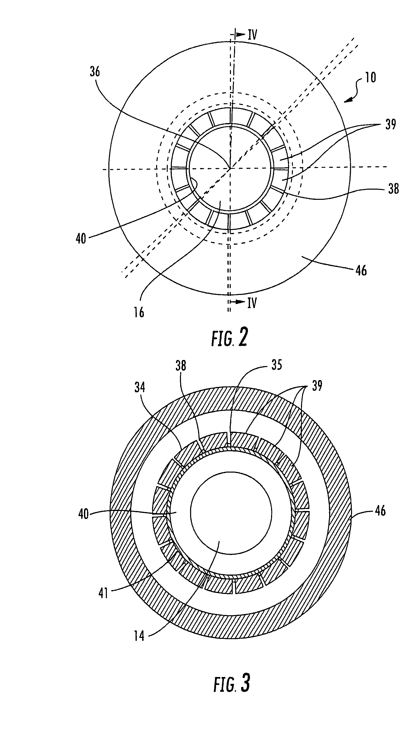
[0059]To adjust the inner diameter of tapered body portion 224 of nozzle body 218, nozzle 210 similarly includes an adjustment tip 246. Adjustment tip 246 comprises a conical-shaped body that is threaded onto adapter 242 and includes a tapered wall 248 spaced from tapered wall 234 with a recessed portion 249 that forms a shoulder 250 adjacent and spaced inwardly from its outer end. Recessed portion 249 contacts the outer ends of the tapered wall's fingers or beams 239 and forms a ramped or cam interface with beams 239. In the illustrated embodiment, each of the beams includes a ramped surface 252, such as a wedge-shaped end, that provides a contact surface for recessed portion 249 of adjustment tip 246. In this manner, when adjustment tip 246 is rotated about coupler 242, recessed portion 249 will translate along ramped surfaces 252, which will cause fingers or beams 239 to compress inwardly when adjustment tip 246 is retracted onto coupler 242 but will allow fingers or beams 239 to...
fifth embodiment
[0066]Referring to FIGS. 15 and 16, the numeral 410 generally designates the nozzle of the present invention. Nozzle 410 is similar to nozzles 210 and 310 and include a nozzle body 418, an adapter 442 for mounting a valve 462 to nozzle body 418, and a second adapter 468 for receiving a hose coupler for mounting nozzle 410 to a hose.
[0067]In the illustrated embodiment, nozzle body 418 includes a cylindrical body portion 422 and a tapered body portion 424, both with fixed diameters. The flexible wall in nozzle 410 is provided by membrane 440. Membrane 440 is mounted to the inlet end of cylindrical body portion 422, for example, by molding, and extends through the passage 430 of tapered body portion 424 to form flow passage 416. In this application, similar to nozzle 110, when membrane 440 is pressurized, membrane 440 will expand radially outward until it reaches the inner surface 424a of tapered body portion 424. For further details of nozzle 410, reference is made to the previous emb...
PUM
 Abstract
Description
Claims
Application Information