Adjustable lighting apparatus

Active Publication Date: 2011-07-05
LSI INDS
View PDF32 Cites 131 Cited by
  • Summary
  • Abstract
  • Description
  • Claims
  • Application Information

AI Technical Summary

Problems solved by technology

Retrofitting LEDs into an existing luminaire or housing can raise issues related to positioning and securing the LEDs or PCBs into the housing or luminaire, to providing the correct and adequate power and controls for the LEDs, and to maintaining the appropriate appearance and aesthetics of the luminaire.

Method used


Image

  • Adjustable lighting apparatus
  • Adjustable lighting apparatus
  • Adjustable lighting apparatus

Examples


Embodiment Construction

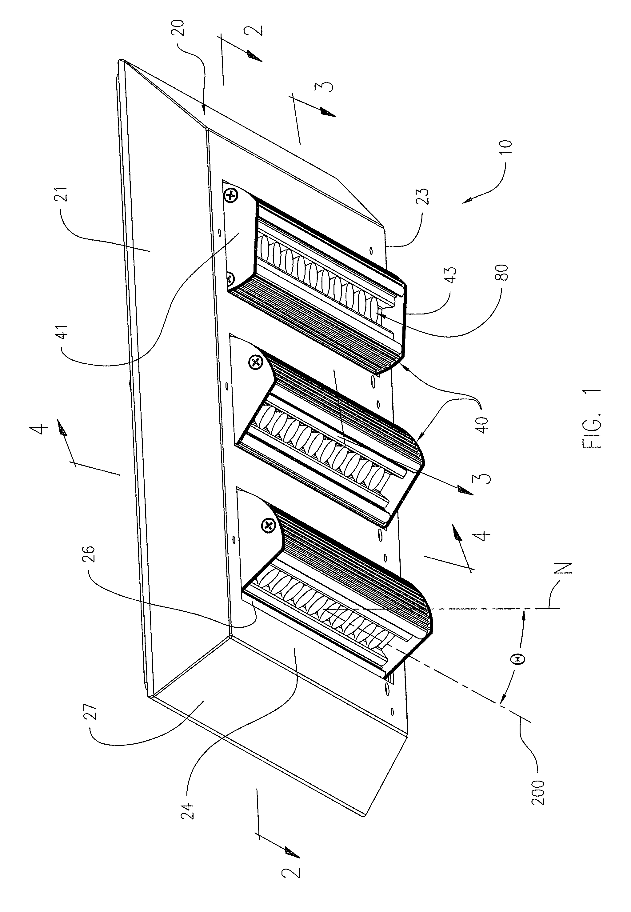
[0021]Referring now to the drawings, FIG. 1 shows a perspective view of a preferred lighting apparatus 10 structure of the present invention, including a housing 20 and a plurality of light cartridges 40 that are pivotally affixed to the housing 10 along their respective longitudinal axes, in order to pivot the light emitted by a plurality of light sources positioned within each of the light cartridges 40. The light cartridge 40 is shown having endplates 41 and 43 at opposed ends of the light cartridge associated with the opposed ends 21 and 23 of the housing in a pivoting manner, as described herein below.

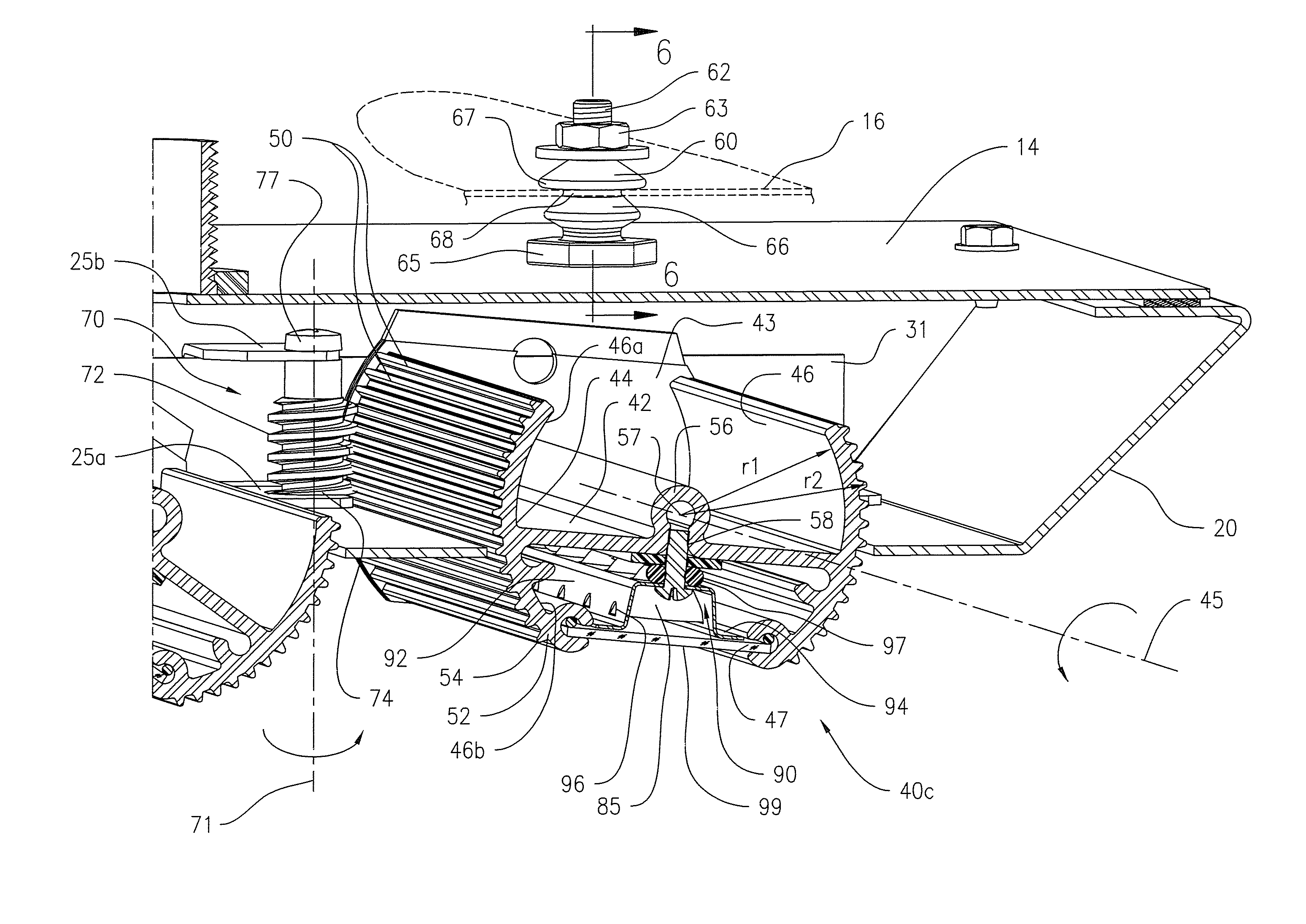
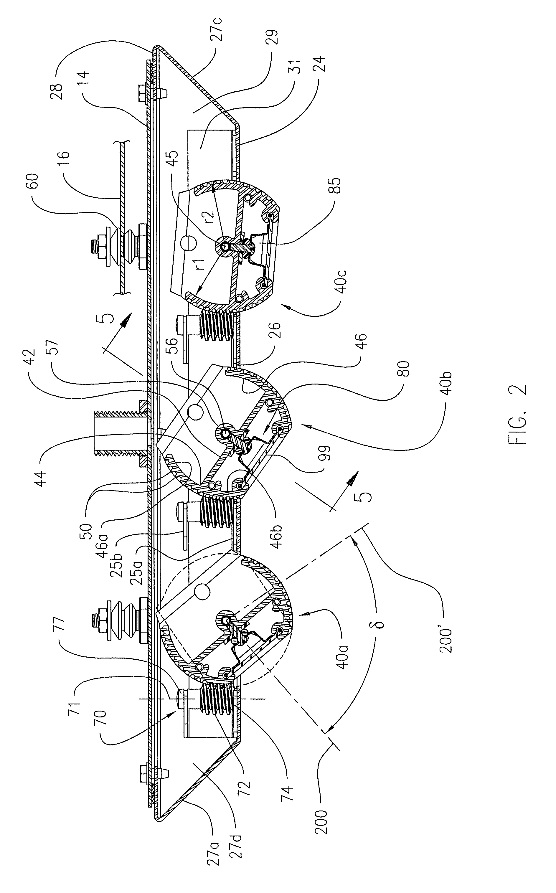
[0022]Referring to FIG. 2, the housing includes a base plate 24 having a plurality of substantially rectangular openings 26 through which a portion of the light cartridge 40 extends. The base plate 24 and a plurality of sidewalls 27 surrounding the base plate define an internal cavity 29 within the housing. The base plate can be an integral part of, or a separate element affixed t...


PUM


Abstract

A lighting apparatus having a pivotable light cartridge for positioning and directing the light output of a plurality of light sources, the light cartridge including an elongated base oriented along the longitudinal axis, a pivot at the opposed first and second ends of the light cartridge along the longitudinal axis, a plurality of light sources, and an longitudinal wall extending from the lateral edge of the base, the wall including a plurality of spaced-apart, radially-extending ribs, each having a distal edge. A rotatable worm gear having a helical thread is positioned in mechanical engagement with a portion of the distal edges of the plurality of ribs, so that rotation of the worm gear with a hand tool effects pivoting of the light cartridge along the longitudinal axis.

Description

FIELD OF THE INVENTION[0001]The present invention relates generally to luminaires and other light fixtures and, more particularly, to a lighting apparatus facilitating adjustment of the direction of the light sources and, therefore, the light emitted from the lighting apparatus. Although useful with most light sources, the present invention is particularly useful with light emitting diodes.BACKGROUND OF THE INVENTION[0002]As advances have been made in the quality and energy efficiency of light emitting diodes (LEDs), the production cost of LEDs has gone down, and LEDs are being commonly used in a wide variety of area lighting applications. Initial efforts to incorporate LEDs into lighting fixtures have involved retrofitting LEDs into conventional luminaires or onto or into the shape of conventional lighting lamps.[0003]More recently, luminaires are being designed to account for the function and specifications of LEDs. LEDs are typically combined together in arrays onto printed circu...

Claims


Application Information

Patent Timeline
Patent Type & Authority Patents(United States)
IPC IPC(8): F21V21/30
CPCF16B5/0258F21S8/04F21V5/04F21V7/0091F21V17/02F21V17/12F21V17/164F21V21/02F21V21/30F21V29/773F21S2/005Y10T16/05F21S4/003F21Y2101/02F21Y2103/003F21S4/20F21Y2103/10F21Y2115/10
Inventor BOYER, JOHN D.
Owner LSI INDS
Why Eureka
Try Eureka