

Seismograph system
a seismograph and system technology, applied in the field of seismograph systems, can solve the problems of high cost and bulkyness of seismograph systems, and achieve the effect of improving accuracy and reducing the size of the seismograph
- Summary
- Abstract
- Description
- Claims
- Application Information
AI Technical Summary
Benefits of technology
Problems solved by technology
Method used
Image

Examples
Embodiment Construction
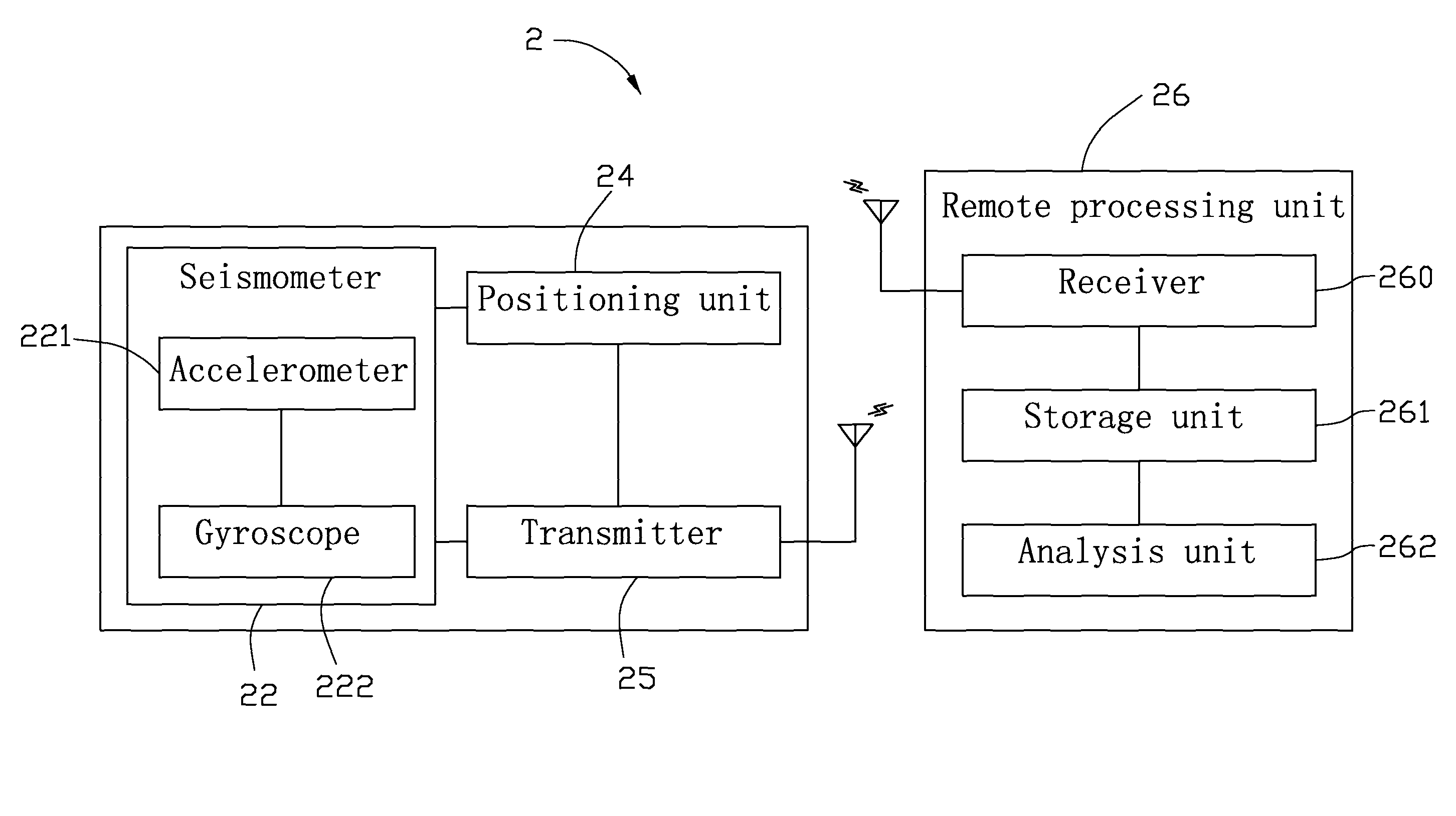
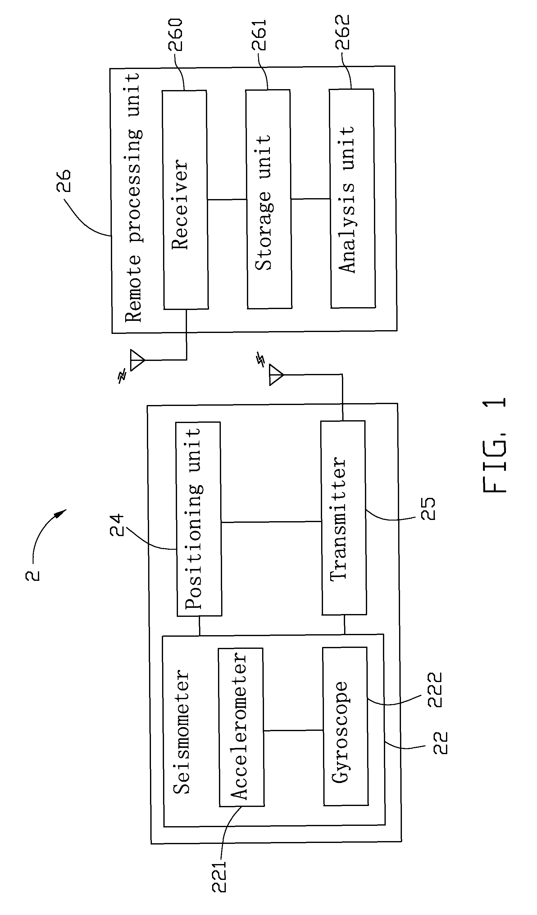
[0009]Referring to FIG. 1, a seismograph system 2, according to an exemplary embodiment, includes a seismometer 22, a positioning unit 24, a transmitter 25, and a remote processing device 26. The seismometer 22, the positioning unit 24, and the transmitter 25 are positioned at a detecting site. The remote processing device 26 is positioned at a remote site.
[0010]The seismometer 22 includes a micro electromechanical system (MEMS) accelerometer 221 and a MEMS gyroscope 222. The MEMS accelerometer 221 is configured for measuring an acceleration of the movement of the earth at the detecting site. The MEMS gyroscope 222 is configured for measuring an angular velocity of the movement of the earth at the detecting site.
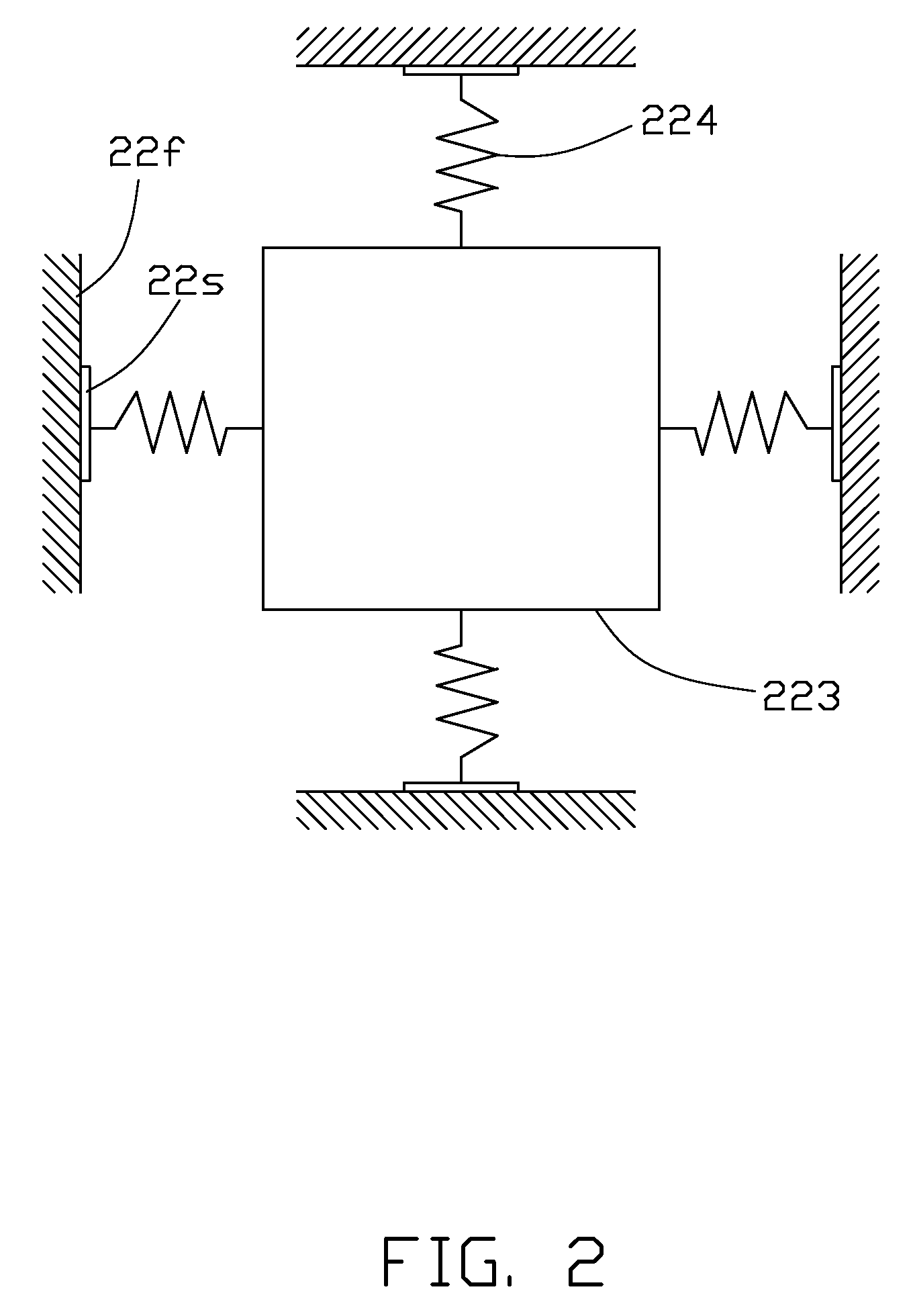
[0011]Referring to FIG. 2, to provide a better understanding of the working principle of the seismometer 22, the seismometer 22 can be understood by visualizing a weight-spring model (not labeled). The weight-spring model includes a frame (not labeled), a weight 223, four sp...
PUM
 Abstract
Description
Claims
Application Information